Testing High-RPM Electric Motors: Essential Equipment
Most facilities confidently test standard motors—then face a crisis at 30,000 RPM. Dynamometers fail. Measurements scatter. Safety margins disappear. The equipment you trust becomes inadequate the moment precision matters most. Capturing thermal and vibration data simultaneously separates facilities that truly understand their motors from those merely guessing. Your measurement accuracy directly determines whether your motor succeeds or catastrophically fails.
Match Test System Specs to Your Motor’s Operating Envelope
Success in high-RPM electric motor testing hinges on selecting dynamometer systems whose technical capabilities align precisely with the motor’s performance demands. Your test equipment must accommodate the motor’s maximum speed rating, torque output, and electrical parameters across its entire operating range.
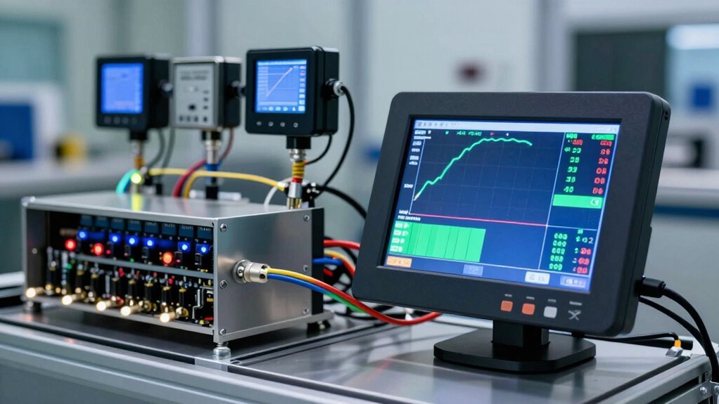
High-speed systems rated for 80,000 RPM or beyond guarantee accurate speed measurement and load simulation without constraint. Torque measurement accuracy of ±0.05% to ±0.1% full-scale deflection captures motor efficiency data reliably during active testing. Comprehensive real-time monitoring software integration enables simultaneous analysis of temperature rise, vibration, and noise characteristics throughout the test cycle. Our cutting-edge software solutions provide seamless data acquisition and performance visualisation for comprehensive motor analysis.
Simultaneously, AC current measurement spanning 0.020-40.00A and voltage ranges from 3.0-500V provide thorough electrical parameter tracking.
Four-quadrant inverter control enables bidirectional operation, essential for regenerative testing scenarios. Strain gauge load cells deliver high-resolution data even at low loads, guaranteeing your motor’s complete performance envelope receives detailed analysis.
Dynamometers: Choosing the Right Braking System for 30,000+ RPM
When testing electric motors operating at 30,000+ RPM, selecting the appropriate braking system becomes critical to both measurement accuracy and equipment longevity.
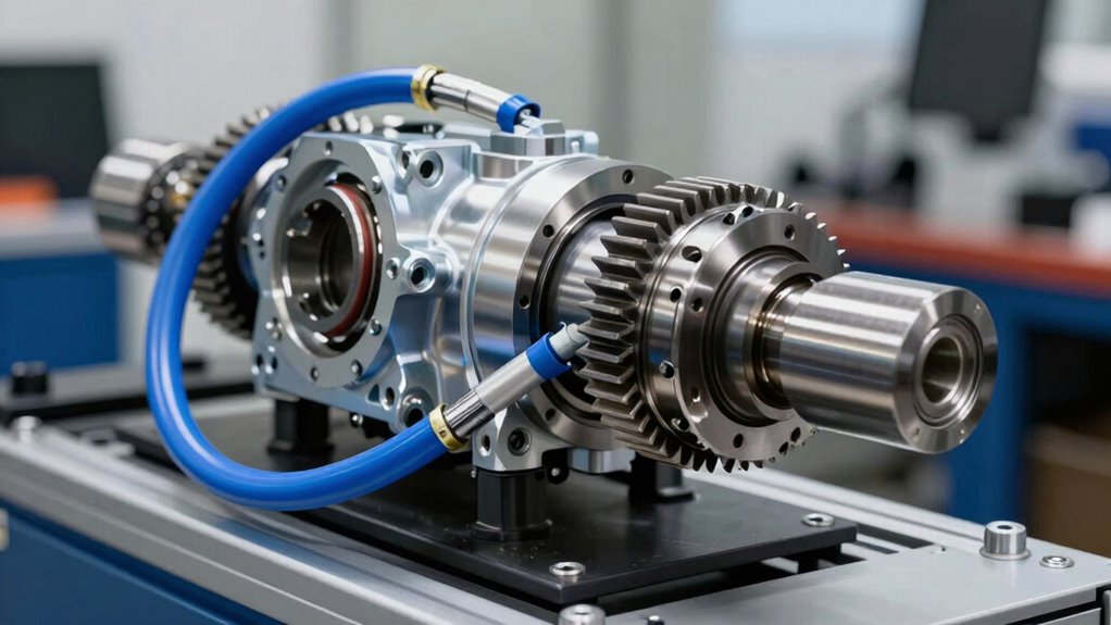
Eddy-current braking systems emerge as the preferred choice for high-speed applications, offering compact designs with low rotor inertia that enable operation well beyond 10,000 RPM. To achieve even higher performance specifications, gearbox reduction ratios such as those used in advanced dynamometer designs can further extend operational capabilities while maintaining precise torque measurement. Hyper Power International’s dynamometer systems are engineered with advanced technology to meet these demanding testing requirements.
Meanwhile, powder brake load control provides an alternative for applications requiring precise torque modulation across varying speed ranges.
Comprehending the operational strengths of each technology guarantees that test engineers can match their dynamometer configuration to the motor’s specific performance envelope without compromising data integrity or component reliability.
Eddy-Current Braking Systems
At the heart of modern high-RPM dynamometer technology lies eddy-current braking, a sophisticated yet gracefully simple approach to absorbing and measuring engine power without mechanical contact. This system generates opposing torque through changing magnetic fields in conductive material, creating braking efficiency that scales proportionally with velocity.
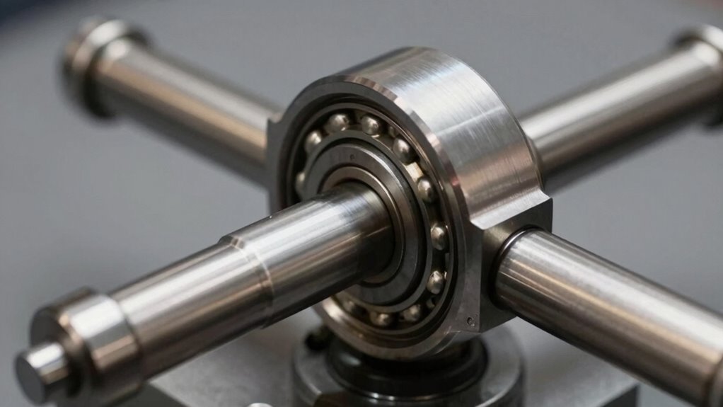
Unlike mechanical alternatives, eddy-current braking eliminates friction wear, making it ideal for sustained 30,000+ RPM testing. Liquid-cooled, low-inertia configurations manage extreme speeds while maintaining precise load control. The frictionless operation enables rapid acceleration adjustments from near-zero to maximum RPM without damaging components. Our team of installation professionals ensures your dynamometer is configured and calibrated for optimal performance from day one.
Energy converts directly to heat through the rotor, requiring effective cooling systems at sustained high speeds. Proper maintenance every 6-12 months, including bearing greasing and debris cleaning, ensures longevity and reliability of the braking system. The adjustable magnetic field—controlled via excitation current—allows operators to apply variable loading for steady-state performance measurement and efficiency analysis through personalised training tailored to your operational needs.
Powder Brake Load Control
Powder brakes represent a fundamentally different approach to high-RPM dynamometer testing, one that employs electromagnetic principles rather than mechanical friction or eddy currents. By suspending ferromagnetic particles in oil, these systems generate precise braking torque through controlled electrical current, enabling professionals to achieve exact load control across demanding RPM ranges.
The powder brake advantages extend beyond simple torque generation. Response times notably outpace mechanical alternatives, critical for rapid load adjustments during transient testing phases. Both the WB 23 and WB 27 models demonstrate torque accuracy of ± 0.2 % full scale, ensuring reliable measurements for high-speed motor evaluation. These tailored solutions are engineered to meet the unique testing needs of high-performance applications.
Load control techniques capitalise on the linear torque-to-current relationship, streamlining calibration procedures and eliminating drift common in traditional systems.
Oil circulation integrated into the housing dissipates heat continuously, maintaining thermal stability throughout extended test cycles.
Thermal sensors monitor temperature in real-time, triggering automatic current reduction when critical thresholds approach, ensuring equipment longevity and test repeatability for high-performance motor applications.
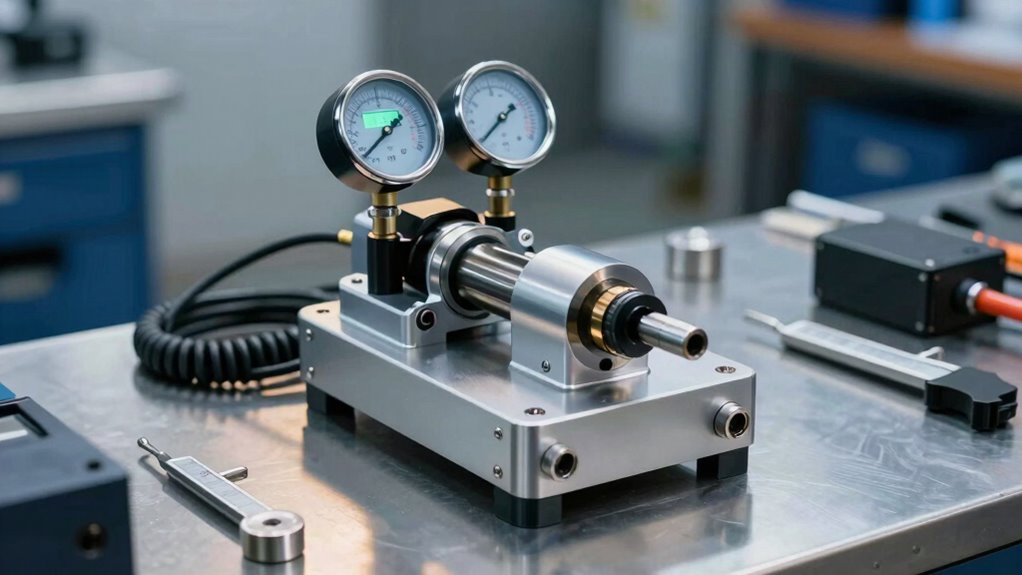
Torque and Speed Measurement Accuracy Above High RPM
At rotational speeds exceeding 30,000 RPM, traditional measurement methods struggle to capture the precise torque variations and instantaneous speed data that electric motor performance demands.
High-speed torque transducers, such as the T40HS model rated for 45,000 RPM, combined with high-bandwidth instrumentation capable of 6 kHz frequency response, enable engineers to distinguish genuine torque fluctuations from electrical noise and mechanical vibrations. Our state-of-the-art testing facilities ensure that high-frequency data acquisition systems maintain precision even when monitoring rapid fluctuations in motor output.
Establishing reliable calibration standards at these extreme speeds guarantees that dynamometer readings remain repeatable and scientifically valid across different testing environments and load conditions. Rotary torque sensors serve as essential auditing tools for verifying motor output torque accuracy throughout the testing process.
High-Speed Dynamometer Precision
Precision measurement at raised RPM levels represents one of the most demanding challenges in modern automotive testing, where even fractional deviations in torque or speed data can compromise the validity of entire test runs.
High-speed sensors and precision instrumentation form the backbone of reliable dynamometer systems, enabling operators to capture accurate performance metrics across extreme operational ranges.
Leading dynamometer platforms deliver exceptional measurement capabilities. The Magtrol WB Series achieves torque accuracy of ±0.2% full scale with speed measurement precision of ±0.06% up to 100,000 rpm, utilising air-bearing systems that minimise friction.
The AVL Performance Line handles speeds to 30,000 rpm with torques reaching 32,000 Nm, employing modular SPECTRA™ technology for consistent accuracy.
These advanced systems guarantee that electric motor testing produces reliable, repeatable data essential for performance validation and optimisation. Real-time performance evaluations enable continuous monitoring throughout the testing process, allowing operators to make immediate adjustments and capture comprehensive insights into motor behaviour under extreme conditions.
Real-Time Torque Monitoring Systems
Contemporary electric motor testing demands measurement systems capable of capturing accurate torque and speed data across extreme rotational velocities, where traditional contact-based sensors often struggle with friction losses and signal degradation.
Advanced sensor technology addresses these challenges through innovative designs that eliminate bearing friction while maintaining precision at speeds exceeding 20,000 RPM.
The AxialTQ™ system enables dual-motor dynamometer testing with simultaneous high-accuracy data collection, essential for thorough EV powertrain evaluation.
Contactless torque sensors deliver measurements spanning 1 Nm to 500 kNm without mechanical wear, ensuring consistent reliability across extended testing sessions.
These systems provide instantaneous torque and power feedback through universal interfaces, allowing engineers to characterise motor performance with clinical precision.
Real-time monitoring capabilities convert raw rotational data into actionable intelligence, supporting the rigorous validation requirements of modern electric vehicle development.
Proactive system monitoring through advanced diagnostic tools ensures that high-RPM testing environments maintain optimal performance and detect potential measurement degradation before it impacts test validity.
Calibration Standards At Extreme Speeds
While real-time torque monitoring systems provide the foundation for capturing accurate data during electric motor testing, the validity of those measurements depends entirely on rigorous calibration protocols that account for the unique challenges posed by high-RPM operation.
High-speed environments introduce variables that compromise measurement accuracy without proper calibration techniques. Speed thresholds create thermal and electrical constraints that shift operational limits, requiring flexible calibration models fitted across multiple RPM points.
Professionals employ standardised approaches to maintain precision:
- Multi-point speed calibration using high-speed cameras recording at 18,002.5718 fps across calibration points from 510 to 2,025 rpm
- ASTM protocols for torque measurement with 213-point verification ensuring repeatability
- Model-based voltage and current limit adjustments accounting for DC bus and thermal limits
These calibration standards guarantee measurements remain scientifically valid, enabling confident performance analysis across the entire high-RPM range. Pursuing professional certification in dynamometer technology ensures technicians maintain the expertise necessary to implement these advanced calibration methodologies correctly.
CT/PT Calibration and Voltage Precision in High-Speed Motor Testing
When testing high-RPM electric motors on dynamometer systems, current converters (CTs) and potential converters (PTs) serve as the foundation for accurate electrical measurements. These devices isolate operators from high-power circuits while enabling instantaneous power calculation through the P=I*V formula, ensuring CT/PT accuracy remains critical to reliable results.
Voltage stability depends on independent automated phase voltage balancing, which produces low-distortion three-phase outputs essential for efficiency testing. Calibration standards like JJG313-94 and IEEE C57.13.1 verify CT accuracy ratings, detect shorted turns, and confirm winding integrity through thorough testing protocols.
Modern calibrators achieve ±0.1% ratio accuracy, with LCD780 power analysers offering 0.07% R+R precision across multiple voltage and current ranges. Grounding strategies during high-voltage testing minimise ratio errors, while gapless four-quadrant measurement improves accuracy on distorted waveforms, providing the scientific validity professionals demand.
The precision demanded by high-RPM electric motor testing extends beyond the dynamometer’s mechanical systems into the digital domain, where data acquisition becomes the critical bridge between raw performance and actionable engineering perceptions.
Data acquisition forms the essential bridge between raw sensor information and actionable engineering insights in high-RPM motor testing environments.
Real-time logging systems capture essential metrics throughout testing cycles, enabling engineers to correlate throttle inputs with performance outcomes.
Critical Data Logging Elements:
- High-speed sampling at 1 MS/s with 10-12 bit resolution captures motor temperature, voltage, ESC conditions, and RPM across multiple channels simultaneously.
- Field-oriented control loops operating above 20 kHz provide precise torque measurement and energetic performance monitoring during acceleration phases.
- Cloud-based data visualisation platforms enable immediate performance optimisation analysis, allowing engineers to identify voltage effects and efficiency trends lap-by-lap.
This integrated approach converts raw sensor data into meaningful observations, supporting informed tuning decisions and thorough performance validation across demanding high-RPM applications. Regular software updates ensure your data logging systems maintain peak accuracy and access to the latest analytical capabilities for evolving testing requirements.
Thermal and Vibration Diagnostics at Maximum Motor Speed
Beyond the digital precision of real-time data logging, the physical health of high-RPM electric motors demands continuous monitoring through thermal and vibration analysis, two interconnected diagnostic disciplines that reveal what raw performance numbers cannot.
Thermal imaging captures heat signatures at maximum speed, exposing electrical faults like loose connections and mechanical issues such as bearing degradation. Every 10°C rise above design temperature halves winding insulation life, making early detection critical.
Vibration analysis simultaneously measures torque and performance drops, identifying misalignment and excessive oscillation that damage components.
Professional technicians combine both approaches during load testing, establishing baseline thermal profiles under normal high-load conditions. Warm couplings in infrared images signal misalignment, while harmonic mode simulations validate mechanical integrity at 60,000 RPM.
This integrated diagnostic strategy guarantees motors operate safely within design parameters, protecting long-term performance and reliability.
NEMA and Safety Standards for High-RPM Motor Test Systems
As high-RPM electric motors push towards operational limits, regulatory structures like NEMA MG1 become essential guardrails that guarantee both safety and performance consistency.
These standards establish critical benchmarks for manufacturers and testing professionals alike, ensuring that equipment operates reliably within defined parameters.
Key Safety and Compliance Requirements:
- Voltage and frequency tolerances must remain within NEMA-specified ranges (±10% voltage variation at rated frequency, ±5% frequency variation at rated voltage) to prevent motor degradation and safety hazards.
- Nameplate specifications require complete performance data, including rated speed, horsepower, insulation class, and service factor, enabling operators to perform NEMA compliance testing accurately.
- Temperature rise limitations and altitude derating formulas protect insulation integrity, preventing thermal failures during extended high-RPM operations.
Adherence to these testing regulations protects both equipment and personnel while validating performance standards across diverse industrial applications.