Meta Description:
Most EV dyno facilities are getting thermal management wrong—and it’s silently corrupting their performance data. While battery temperatures between 15-30°C are non-negotiable, outdated cooling approaches continue to dominate testing floors, creating invisible failures that invalidate months of validation work. Heat pumps and modular circuit separation exist, yet remain underutilised across the industry. Discover why thermal negligence is sabotaging your results and what actually works.
Battery Temperature Control: The Dyno Make-or-Break Factor
Electric vehicle batteries operate within narrow thermal windows, and maintaining precise temperature control during dynamometer testing separates reliable validation from costly failures.
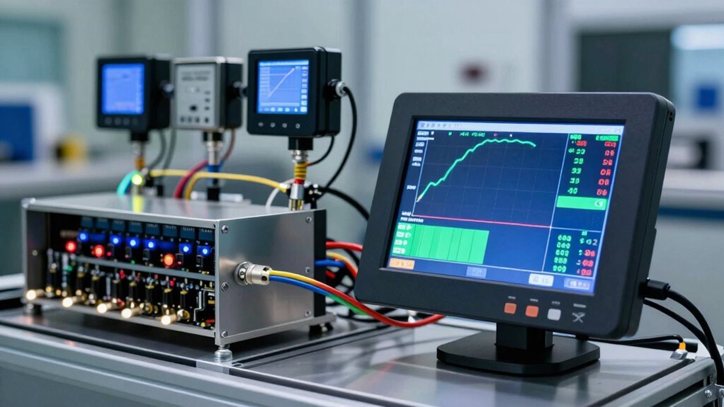
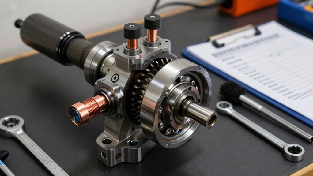
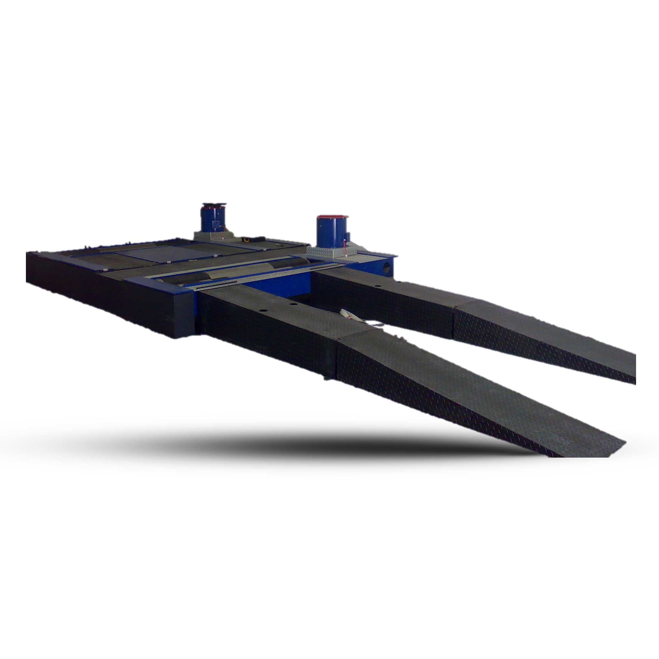
Advanced cooling innovations, such as PRESTO A45 units operating from -45°C to 250°C, enable engineers to simulate real-world conditions with clinical accuracy. These systems monitor critical parameters including cell voltages, inlet and outlet temperatures, and thermal hotspots throughout testing cycles. The PRESTO A45’s flow meter and fluid by-pass maintain stable test bed temperatures while efficiently managing cooling requirements across different load conditions.
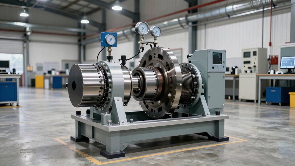
Thermal efficiency directly impacts battery performance and longevity. When temperatures deviate outside acceptable ranges, lithium-ion cells degrade rapidly, risking thermal runaway or catastrophic failure. Our state-of-the-art testing facilities utilise advanced dynamometer technology to ensure precision and reliability throughout every thermal validation cycle.
Dyno-specific cooling systems maintain consistent temperature distribution across battery packs, preventing localized overheating that undermines development validation.
Professional testing facilities recognise that superior thermal management during dynamometer runs delivers repeatable, scientifically valid data. This precision protects vehicle reliability and accelerates innovation timelines across the EV industry.
Optimal Battery Temperature for Dyno Testing: 15-30°C
Maintaining a battery temperature between 15-30°C during dynamometer testing guarantees repeatable, scientifically valid performance metrics that reflect real-world conditions.
Within this thermal window, batteries deliver their highest usable energy output, while the chassis dynamometer can isolate drivetrain efficiency without temperature-induced variables skewing results.
This controlled approach simultaneously reduces thermal stress on battery chemistry, preventing accelerated degradation and enabling more reliable long-term performance assessments across multiple test cycles. Hyper Power International’s precision testing services ensure that thermal management protocols are properly implemented throughout all dynamometer testing procedures. Similar to how security services protect digital infrastructure from threats, proper thermal management safeguards battery systems from performance degradation during intensive testing protocols.
Why does battery temperature matter so much when testing electric vehicles on a dynamometer? The temperature impact on battery performance directly determines the validity and repeatability of dyno test results, making thermal control essential for accurate performance enhancement.
Battery voltage, capacity, and efficiency fluctuate markedly outside ideal ranges. At 15-30°C, EVs achieve their rated range without thermal management penalties, providing baseline performance data. Below 15°C, capacity drops and charging times extend, while above 30°C, voltage decreases and thermal stress increases. Extreme temperatures can shorten battery lifespan, necessitating careful temperature monitoring during all dyno test phases.
Controlled dyno chambers maintain these ideal conditions, eliminating environmental variables that compromise measurements. Our dynamometer technology provides the precision needed for consistent thermal environment control during testing. SAE J1634 protocols require temperature consistency, ensuring test repeatability across sessions.
This precision enables technicians to isolate genuine vehicle performance from thermal artefacts, providing reliable data for performance enhancement and regulatory compliance.
Thermal Stress Reduction Benefits
Precision in battery temperature control during dynamometer testing represents the foundation of reliable EV performance data, and the 15-30°C ideal range delivers measurable advantages that extend far beyond a single test session.
Operating within this prime window considerably reduces thermal stress on battery materials, preventing the structural damage caused by extreme temperature fluctuations. When cells remain at consistent temperatures, lithium ion flow stabilises, enabling accurate power measurements and preventing dendrite growth that triggers internal short circuits. Material transitions within battery assemblies often represent fatigue sources that dynamic pressure cycling can reveal during accelerated durability testing. Our proactive system monitoring ensures that temperature parameters remain within specification throughout extended test protocols.
Battery safety improves greatly in this controlled environment. The 15-30°C range minimises thermal cycling stress, protecting welds, press fits, and adhesive bonds from accelerated fatigue.
Testing at prime temperatures ensures data repeatability while extending equipment lifespan, making it a strategic investment for professional dynamometer facilities seeking reliable, scientifically valid results.
Heat Pump Technology: Dyno Battery Temperature Control Under Load
Heat pump systems maintain battery temperatures within the ideal 15-30°C range during dynamometer testing by actively adjusting refrigerant circulation and extracting waste heat from motor operation.
Unlike static heating methods, these systems respond in real-time to load conditions, using PID controllers to balance thermal demands between the battery pack and cabin while the vehicle undergoes rigorous performance simulation.
This active temperature regulation guarantees consistent, repeatable test results while maximising the efficiency advantages that heat pumps provide over conventional resistance heaters, particularly during extended dyno cycles that generate substantial thermal stress. Industrial-grade water-cooled chillers are essential for delivering process fluid temperatures as low as -25°F year-round to support reliable results for vehicle performance assessments.
Heat Pump Operational Dynamics
How do engineers maintain precise battery temperatures when electric vehicles undergo rigorous dynamometer testing under extreme load conditions?
Heat pump efficiency proves critical during dyno operations, where refrigerant flow management directly impacts battery performance.
Modern heat pump systems employ PID controllers that adjust compressor demand based on real-time battery temperature targets.
This flexible regulation guarantees consistent thermal conditions throughout testing cycles, preventing overheating or excessive cooling that compromises battery health.
The refrigerant circulates through dual loops—one for battery cooling and another for cabin heating—enabling versatile heat distribution.
Engineers can supply multiple chilled water setpoints simultaneously, accommodating various test scenarios from standard protocols to extreme condition simulations.
Gas injection technology enhances refrigerant mass flow, maintaining vapour density even during low-temperature operations.
This capability supports 24/7 dyno uptime while providing the thermal stability required for accurate performance measurements and reliable long-term battery conditioning.
Regular software updates ensure that heat pump control algorithms remain optimised for evolving testing requirements and peak thermal management performance.
Dyno Load Temperature Regulation
During electric vehicle dynamometer testing, maintaining stable battery temperatures across the full operational range—from idle conditions to maximum load—demands sophisticated thermal management systems that go far beyond passive cooling. Heat pumps transfer energy efficiently between heating and cooling modes, ensuring the battery remains at the critical 65°C setpoint regardless of load intensity. Our installation professionals ensure that your thermal management system is properly calibrated and integrated for optimal performance from day one.
| Operating Condition |
Heat Output |
Cooling Input |
Target Temp |
| Idle State |
1.8 kW |
— |
65°C |
| Partial Load |
0.8 kW |
0.05 kW |
65°C |
| Full Load |
— |
0.14 kW |
65°C |
| Post-Test Cooldown |
— |
Active |
Safe Shutdown |
Dyno load optimisation requires precise cooling system integration that regulates absorber temperatures throughout testing cycles. Post-test protocols mandate 3-minute no-load runs at 30 MPH to safely reduce temperatures before shutdown.
Dyno Coolant Strategies: When to Switch Serial and Parallel Modes
Because hybrid electric vehicles operate through fundamentally different powertrain configurations, their cooling demands shift dramatically depending on which mode is active during dynamometer testing.
Series mode efficiency dominates low-speed operations, where the engine powers a generator independently from vehicle speed, minimising thermal stress through a single energy conversion pathway.
Series mode efficiency minimises thermal stress during low-speed operations through independent engine-generator coupling from vehicle speed.
Parallel mode challenges emerge at higher loads, as direct coupling of the ICE and motor generates simultaneous heat across multiple components, intensifying coolant flow management requirements.
Battery SOC impacts mode selection critically. Above 0.9 SOC, regenerative braking ceases, shifting toward series operation. Below 0.4 SOC, silent mode deactivates entirely, increasing thermal load substantially.
Strategic hybrid powertrain optimisation requires coolant system design that accommodates rapid thermal fluctuations during mode switching, ensuring sustained performance across diverse test protocols and operating conditions. Tailored cooling solutions engineered for specific dynamometer models can address the unique thermal management challenges posed by hybrid powertrains during complex testing scenarios.
Inverter Cooling on the Dyno: Preventing Cross-Component Thermal Coupling
Electric motor inverters generate substantial heat during dynamometer testing, particularly when subjected to high switching frequencies and sustained load cycles. Effective inverter thermal management requires strategic cooling loop design to isolate thermal loads from adjacent dyno components.
Professional testing facilities employ three critical approaches:
- Modular system framework separates inverter cooling circuits from motor and battery thermal paths, preventing heat transfer between components.
- Real-time temperature monitoring using thermocouples and synchronised data acquisition validates thermal models and triggers control shutdowns when limits approach.
- Regenerative energy isolation in AccuDyne systems recaptures over 90% of power while maintaining independent cooling loops.
Silicon carbide converters with FPGA control further reduce thermal coupling risks through minimised switching losses. Advanced diagnostics and analysis services provide real-time performance evaluations to ensure thermal management strategies maintain optimal inverter efficiency throughout extended testing cycles.
This decoupled design method guarantees accurate, repeatable testing results while protecting sensitive electronic components from cross-component thermal interference.
Single vs. Redundant Thermal Loops: System Architecture for Dyno Accuracy
The isolation strategies discussed for inverter cooling represent only one layer of thermal management complexity, because dynamometer testing demands broader structural decisions about how all cooling circuits interact.
Single-loop designs maximise cooling efficiency by integrating all components into one unified system, reducing weight and complexity while achieving rapid thermal response.
Single-loop cooling designs unify all components into one efficient system, reducing weight and complexity while enabling rapid thermal response.
Redundant-loop configurations preserve thermal balance by maintaining separate circuits for disparate temperature needs—power electronics at 60°C versus battery systems at 30°C—preventing problematic cross-component coupling.
Four-way valves enable parallel operation, isolating subsystems like chargers and inverters independently.
On the dyno, water circuits remove heat from both engine and dynamometer, with ambient monitoring ensuring test consistency.
The choice between designs directly impacts measurement accuracy and operational reliability during extended performance testing. Custom dyno solutions offer tailored software integration that optimises thermal management strategies for your specific testing requirements and vehicle configurations.
Five Cooling Failures That Invalidate Dyno Results (and How to Catch Them)
What separates a valid dynamometer run from a compromised dataset often comes down to thermal management—a factor that operators and engineers frequently underestimate until results deviate dramatically from real-world performance.
Thermal failure detection requires vigilance across multiple fronts.
Critical cooling system optimisation failures include:
- Intercooler overheating from inadequate airflow, reducing air density and triggering ECU timing pulls above 4250 RPM
- Coolant temperature spikes causing ECU derating and invalidating baseline measurements between successive pulls
- Motor insulation breakdown from poor ventilation, detected through thermal imaging and insulation resistance monitoring
Professional operators implement redundant thermal loops, peripheral sensor arrays, and continuous monitoring protocols.
These measures capture early warning signs before catastrophic failures occur, ensuring repeatable, scientifically valid results that reflect genuine vehicle performance rather than thermal artefacts.
Dyno Testing: Temperature Management Protocols That Stick
Once thermal variables spiral beyond acceptable ranges, even the most sophisticated dynamometer hardware cannot salvage the integrity of test data.
Successful temperature tracking requires discipline, starting with maintaining coolant outlet temperatures below 160°F and inlet temperatures below 100°F for ideal coolant efficiency.
Type K thermocouples provide granular monitoring across critical points. Engine dynamometer setups employ 16 readings, while chassis systems use 4, capturing coolant, oil, and exhaust gas temperatures simultaneously.
Supply tank sizing determines cooling capacity within 24 hours under standard conditions. Thermostat-activated pumps at 100°F and fans at 105°F prevent thermal drift that causes up to 10% power variation.
Environmental inputs—ambient temperature, barometric pressure, humidity—ensure repeatability across test cycles.
This systematic approach changes temperature management from reactive troubleshooting into predictive control.