Diesel dynamometer testing demands precision that most operators are getting dangerously wrong. While your team focuses on throttle settings and load curves, silent heat damage is degrading measurements and silently shortening equipment life. Airflow requirements, water loop capacity, and thermal management aren’t afterthoughts—they’re the difference between trustworthy data and expensive failures nobody saw coming. Learn what separates workshops running reliable tests from those haemorrhaging money in downtime.
Why Does Airflow Matter in Diesel Dyno Testing?
Airflow in a dynamometer cell functions as the backbone of reliable diesel engine testing, serving multiple critical purposes that directly impact both the accuracy of results and the safety of the operation.
Proper airflow mechanics manage engine heat by carrying away thermal energy from engine surfaces and exhaust systems, preventing dangerous temperature rises that compromise test consistency. Dense, controlled airflow delivers ideal oxygen intake, enabling complete fuel burn and accurate power readings.
Without sufficient airflow, hot air recirculates around the engine, skewing torque and horsepower measurements unpredictably. Temperature control through strategic ventilation guarantees repeatable results across multiple test runs. Website security services like Cloudflare protect testing facilities by blocking potentially harmful automated queries that could disrupt dynamometer operations.
Furthermore, strong airflow prevents hazardous carbon monoxide and exhaust vapour accumulation, protecting operators while maintaining data integrity. Our advanced dynamometer technology enables precise measurement and control of these critical cooling parameters. Professional diesel testing demands this foundational cooling infrastructure.
What CFM Does Your Diesel Dyno Setup Actually Need?
Determining the correct CFM requirement for a diesel dyno setup hinges on matching airflow capacity to engine displacement and the intensity of testing performed, as undersized systems create compounding thermal stress.
The relationship between engine size and CFM demand is not linear—idle conditions require far less ventilation than full-load dynamometer runs, where a cubic-inch displacement multiplied by 4.15 establishes the baseline airflow needed. Many manufacturers exaggerate the airflow capabilities of their cooling fans, so engineering documentation should be consulted to verify actual performance specifications. Our comprehensive parts and maintenance kits ensure your cooling system operates at peak efficiency during all testing phases.
Inadequate CFM circulation leads to dangerous temperature escalation, reduced data accuracy, equipment degradation, and potential safety hazards that compromise both the testing environment and the validity of performance results.
Engine Size To CFM Ratio
The relationship between engine displacement and cooling airflow represents one of the most critical calculations in diesel dynamometer setup, yet it remains frequently misinterpreted or overlooked by operators unfamiliar with the technical requirements.
Engine size directly determines CFM requirements through established formulas. A 4-cycle turbo diesel engine requires cubic inches multiplied by 4.15 for full-load testing, whereas partial-load scenarios demand only 2.05 times displacement. The CAT 3126TA exemplifies this principle, requiring 564 CFM at 439 cubic inches. Boost pressure significantly affects the actual airflow demand, with turbocharged engines requiring substantially higher CFM calculations than naturally aspirated counterparts due to increased absolute pressure ratios.
Dyno cells must supply 10 to 15 times the engine’s calculated CFM for proper cooling efficiency. This airflow optimisation extends beyond combustion air, providing additional cooling circulation around the engine. Precision testing and accurate CFM calculations are essential components of reliable dynamometer systems that ensure consistent and valid test results across multiple runs.
Comprehending this engine size-to-CFM relationship guarantees operators maintain safe temperatures during demanding diesel runs, protecting both equipment and test validity.
Airflow Inadequacy Consequences
When diesel engines run on dynamometers without sufficient cooling airflow, operators face a cascade of operational failures that compromise both equipment safety and data integrity.
Inadequate CFM directly causes heat buildup consequences, allowing exhaust temperatures to exceed safe thresholds while creating dangerous exhaust fume backup conditions. When airflow falls short of design specifications, fumes accumulate in the dyno cell rather than venting properly, posing serious health risks to technicians. Security service protection similar to website access controls can help monitor facility compliance with ventilation standards.
Room pressurisation from poor intake fan design throws off dynamometer readings, rendering test results unreliable. Operators detect exhaust leaks through visible fumes post-run, signalling system failure. Hyper Power’s proactive system monitoring helps identify cooling inadequacies before they compromise equipment or safety.
Heat accumulation damages sensitive equipment and forces premature shutdowns, reducing facility productivity. Professional shops recognise that undersized ventilation systems create liability exposure while compromising the scientific validity of performance testing data.
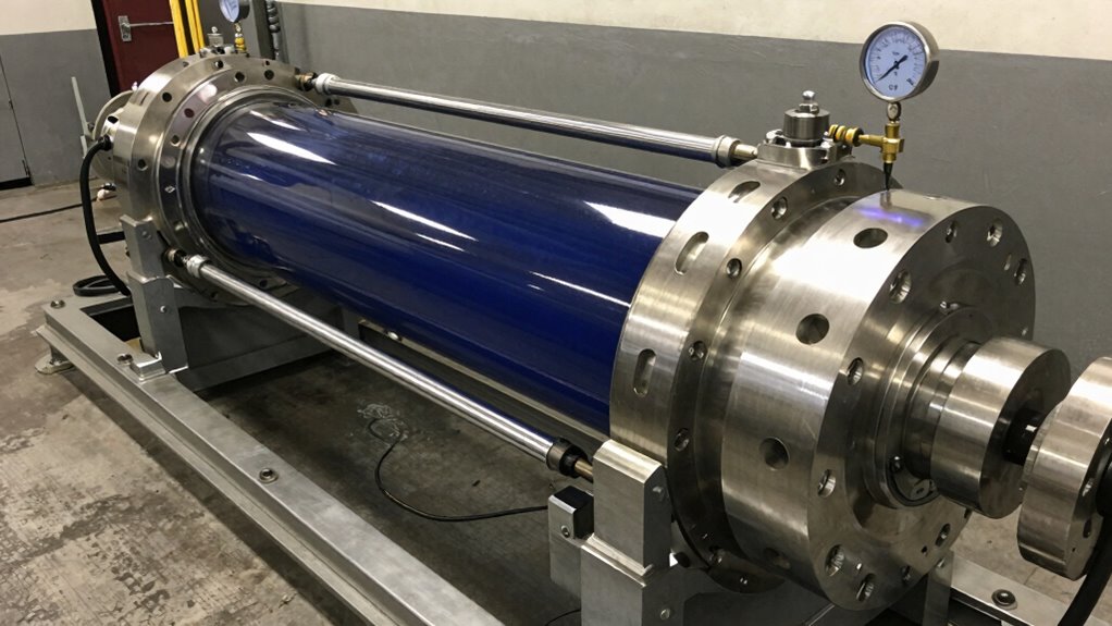
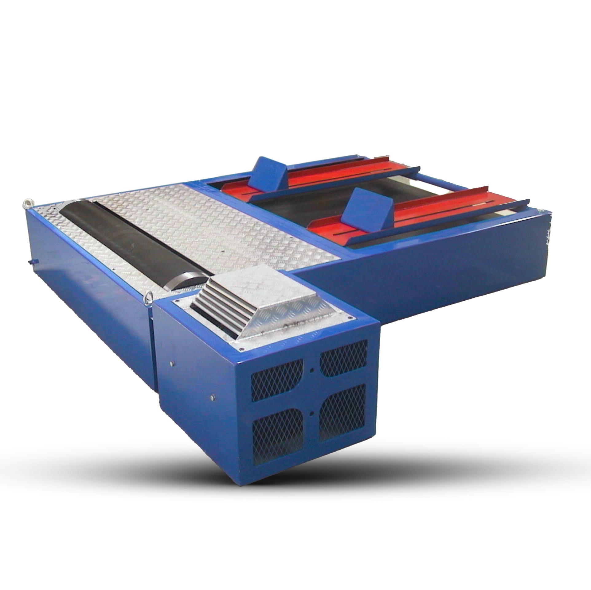
How Water Brake Dynos Cool Under Heavy Load
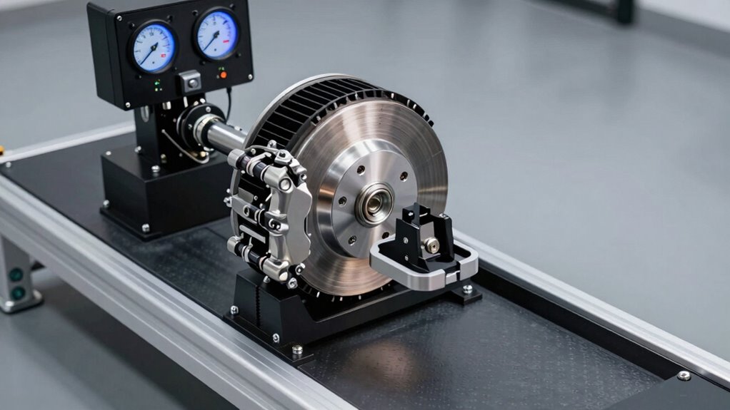
Water brake dynos utilise the thermal capacity of circulating water to absorb and dissipate the tremendous heat generated during high-horsepower diesel testing, with water jackets directing coolant past friction surfaces to continuously remove energy from the braking system.
The housing itself plays a critical role in this thermal management, transferring absorbed heat to the surrounding environment while dual stainless steel valves modulate water flow to maintain ideal operating temperatures even under sustained heavy loads. Real-time data collection during testing processes ensures that thermal parameters remain within optimal ranges. Maintaining a supply water temperature of 85°F (30°C) or cooler is essential to preserve measurement accuracy and prevent performance degradation during extended testing sessions.
Water Absorption and Load
At the heart of effective dynamometer performance lies a fundamental principle: water serves as both the absorption medium and the cooling agent that allows diesel engines to be tested safely under extreme loads.
The water brake absorbs horsepower through resistance, converting mechanical energy into heat. As load increases, water temperature rises proportionally. Proper load management requires maintaining ideal flow rates to prevent thermal runaway. The system must balance absorption capacity with cooling efficiency. Hyper Power’s comprehensive technical support ensures that your cooling systems operate at peak efficiency throughout extended testing sessions.
| Horsepower Range |
Minimum Flow (L/min) |
Inlet Temp (°C) |
Outlet Temp (°C) |
Cooling Priority |
| 100-200 |
4.5-9 |
25-30 |
50-55 |
Moderate |
| 200-400 |
9-18 |
25-30 |
55-58 |
High |
| 400-600 |
18-27 |
20-28 |
58-60 |
Critical |
| 600-800 |
27-36 |
18-25 |
58-60 |
Critical |
| 800+ |
36+ |
15-22 |
58-60 |
Maximum |
Diesel applications demand greater cooling capacity due to sustained high-load testing intervals. Fresh, clean water enhances absorption while preventing component degradation and ensuring test repeatability across multiple runs.
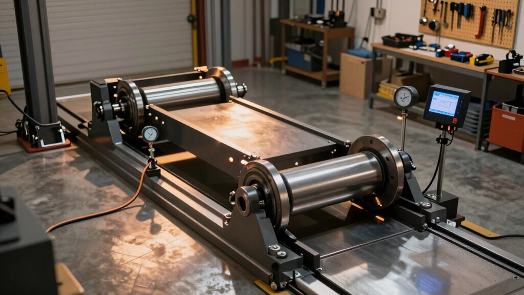
Heat Dissipation Through Housing
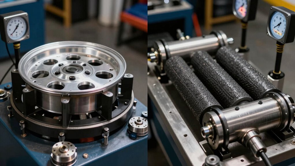
The intricate design of water brake dynamometer housings represents a critical engineering solution to managing extreme thermal loads during diesel engine testing. The housing and jacket design work together to extract heat efficiently, allowing operators to sustain high-power diesel runs without thermal failure.
The cooling mechanism relies on several integrated components:
- Water jacket chambers positioned along friction surfaces to capture and remove generated heat
- Heavy-duty friction material on drive plates that concentrates thermal conductivity where it matters most
- Aggressive rotor fin technology that increases surface area for improved heat transfer
- Brake support structure engineered to withstand rotational forces while maintaining seal integrity
This housing design guarantees consistent thermal performance, enabling professionals to carry out extended testing sessions with confidence and repeatability throughout demanding diesel applications. Hyper Powers’ custom dyno solutions ensure that thermal management systems are tailored to meet the specific heat dissipation requirements of each unique testing scenario.
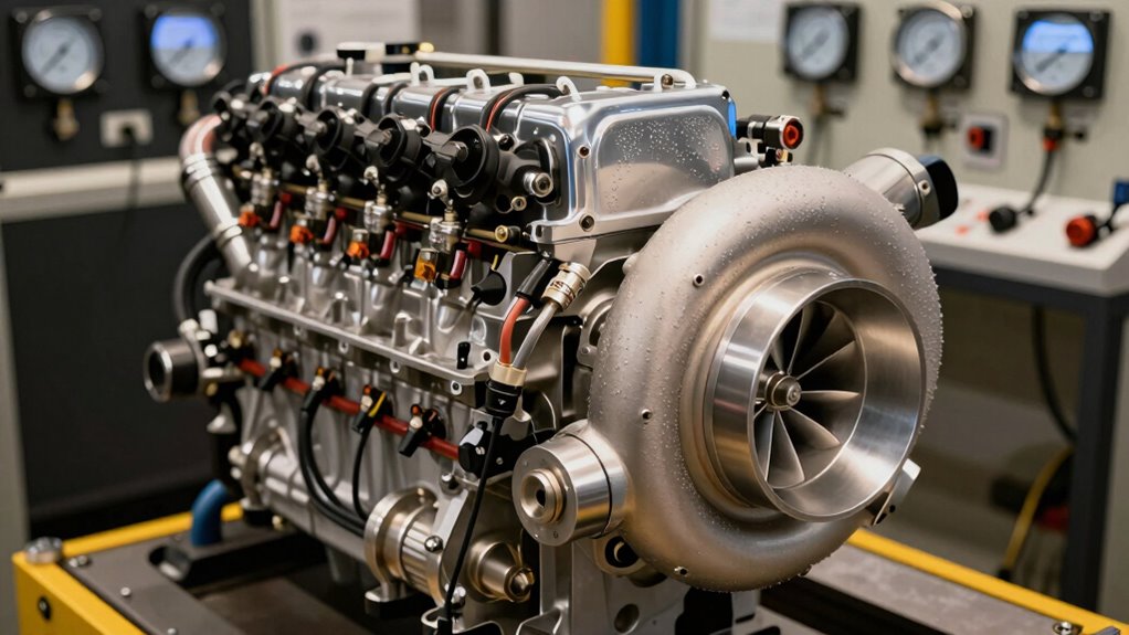
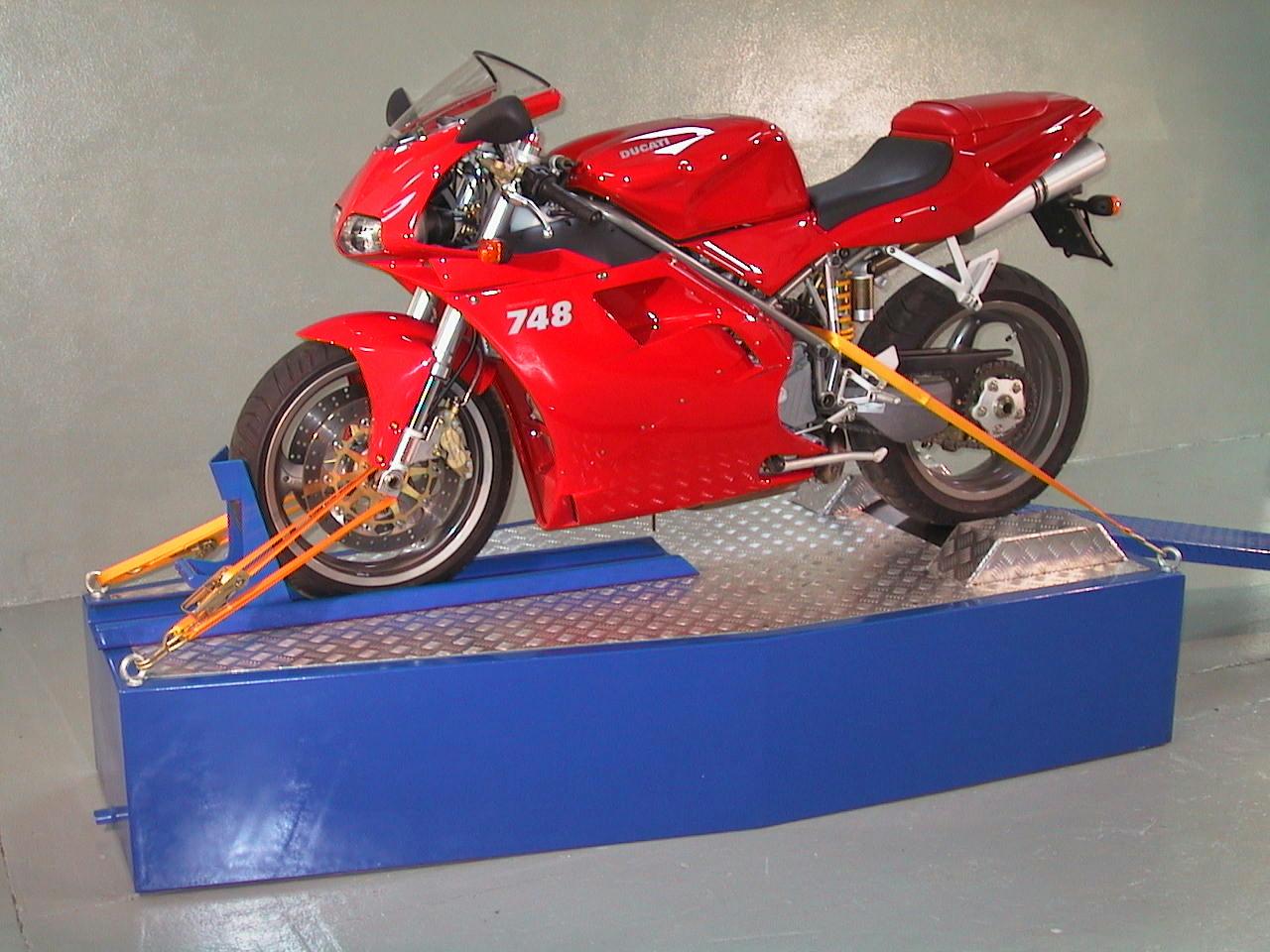
Engine vs. Chassis Dyno Cooling: Which Stays Cooler?
When comparing engine and chassis dynamometers side-by-side, one critical difference emerges immediately: engine dynos consistently maintain cooler operating temperatures than their chassis counterparts. Engine cooling benefits from simplified setups that strip unnecessary accessories and allow unrestricted airflow through basic filtration systems. Chassis efficiency, however, demands the vehicle retain full accessories, bonnets, and complete exhaust systems that trap underbonnet heat.
| Factor |
Engine Dyno |
Chassis Dyno |
Impact |
| Water Temperature |
160°F |
175-180°F |
15-20°F difference |
| Airflow |
Unrestricted |
Limited by body |
Cooling capacity |
| Drivetrain Loss |
Minimal |
15-25% |
Heat generation |
| Accessory Load |
Reduced |
Full retention |
Thermal burden |
Engine dynos maintain 10-20°F cooler conditions, enabling more consistent parts comparisons and stable testing protocols.
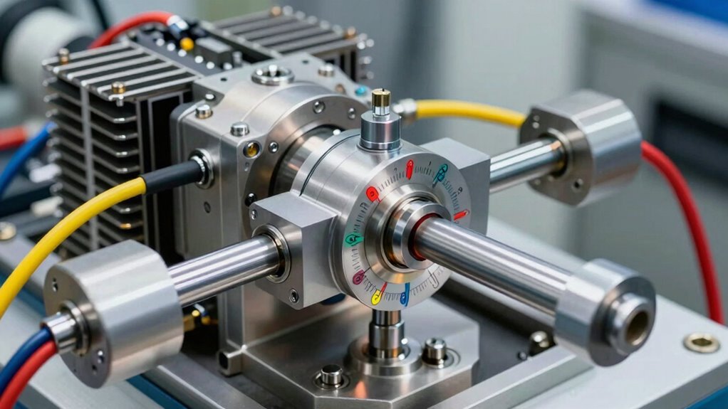
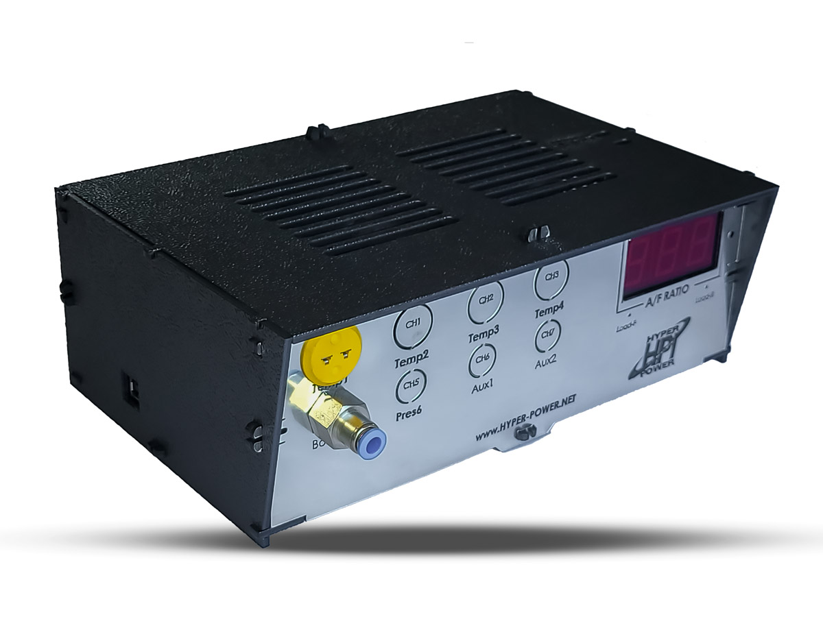
Reading Coolant Temperature to Catch Problems Early
Monitoring coolant temperature during diesel dynamometer runs provides operators with an early warning system that prevents catastrophic engine failure before it occurs. Temperature sensors positioned near the thermostat and threaded directly into the engine block track real-time coolant conditions, transmitting voltage signals to the PCM for continuous engine diagnostics.
Effective coolant monitoring involves:
Effective coolant monitoring uses scanner displays, multimeter testing, audible alarms, and dual-sensor configurations for comprehensive engine protection.
- Scanner live data displays showing output voltage or temperature readings during steady-state loading
- Multimeter resistance testing identifying intermittent faults before dyno runs escalate
- Audible alarms triggering at critical thresholds with customisable warning settings
- Dual-sensor configurations monitoring engine and transmission temperatures simultaneously
PCM feedback regulates fuel injection, ignition timing, and radiator fan activation based on sensor placement accuracy. Regular software updates ensure that your dynamometer’s monitoring systems remain current with the latest diagnostic capabilities and security enhancements.
Early detection prevents overheating, guarantees diesel efficiency, and maintains repeatable testing conditions throughout extended dyno sessions.
How Much Tank Capacity Do You Need for Mapping?
How much cooling capacity does a diesel dynamometer require to safely execute fuel mapping protocols?
Tank capacity directly impacts the success of extended fuel mapping sessions. Water-cooled eddy current dynos demand substantial cooling systems, with tanks positioned outside the test cell to handle recirculating water during high-horsepower runs.
As operators command more fuel through increased rail pressure and pulse widths, engine heat generation rises correspondingly, requiring proportionally larger tank capacity.
For diesel tuning operations achieving 80-100 hp gains from stock baseline power, engineers must ascertain adequate water circulation. A properly sized cooling tank prevents temperature spikes that compromise data accuracy and equipment integrity.
Most professional installations require 15-20 foot square cells, accommodating both cooling towers and distribution lines necessary for sustained mapping work.
Expert calibration techniques ensure that tank capacity planning ascertains repeatable, scientifically valid test results.
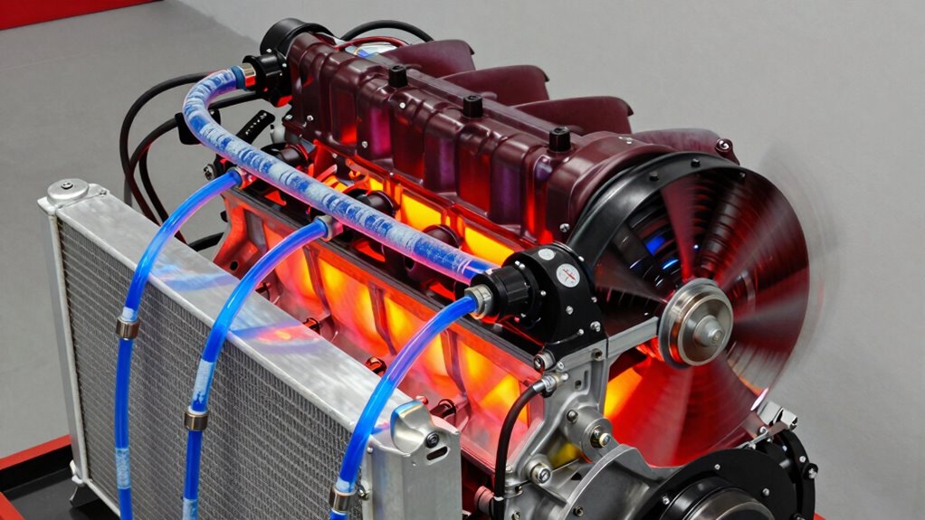
Preventing Water Loop Overheating in Dyno Runs
Because diesel dynamometer systems generate tremendous heat during fuel mapping and performance tuning, controlling water temperature becomes critical to both equipment longevity and data integrity.
The cooling efficiency of your system directly determines how many consecutive test runs remain possible before thermal saturation occurs.
Key temperature management strategies include:
- Maintaining inlet water temperature below 27°C to prevent control instability
- Monitoring outlet temperatures to stay under 71°C, preventing scale buildup
- Limiting temperature rise to 33°C maximum per cycle
- Installing industrial cooling towers or intermediate tanks for heat dissipation
Professionals recognise that exceeding these thresholds risks erratic dynamometer control, engine runaway conditions, and expensive brake repairs.
A properly configured cooling infrastructure guarantees consistent, repeatable data while protecting your investment in high-performance testing equipment. Selecting quality cooling accessories engineered specifically for your dynamometer model ensures optimal thermal management and system reliability during extended testing sessions.
Airflow Ductwork and Fan Sizing for Dyno Rooms
While water cooling systems manage the internal heat generated by the dynamometer brake itself, the dyno room’s airflow infrastructure handles the enormous thermal load expelled by the test engine.
Proper ductwork design guarantees efficient air movement, with inlet systems featuring roof-mounted plenums containing 24-inch filters and 18-inch stainless tubing directing fresh air across the engine.
Fan efficiency depends on correctly sized exhaust ducts, typically 12-inch steel pipe manifolded through room walls, with axial-flow fans extracting contaminated air at the outlet end.
Room dimensions of 12 by 15 feet with 8-to-9-foot ceilings, combined with 28,000 cfm fan capacity, accommodate endurance runs exceeding one hour.
This integrated ventilation system prevents engine bay temperatures from climbing uncontrollably during sustained diesel testing.
When Coolant Temps Spike: Red Flags in Your Cooling System
What separates a controlled diesel dynamometer run from a catastrophic engine failure often comes down to recognising the early warning signs of cooling system distress.
Professionals operating high-performance diesel units must monitor critical indicators that signal underlying problems:
- Coolant leaks from hoses, radiators, or water pumps that reduce system volume and compromise thermal efficiency
- Faulty thermostats stuck closed, blocking coolant flow to the radiator and causing sudden temperature spikes under load
- Clogged radiator passages from debris, rust, or mineral deposits that restrict heat dissipation capability
- Water pump failures evidenced by unusual noise, reduced pressure, or visible seepage during warm-up cycles
Regular inspections before heavy dynamometer loads catch these issues early, preventing expensive engine damage.
Proactive cooling system inspections before high-load operation prevent catastrophic failures and protect critical engine investments.
Maintaining proper coolant type and levels guarantees consistent thermal efficiency throughout demanding test protocols, protecting both equipment investment and operational reliability.