Buying Guides
Dyno Finance South Africa: Easy Funding for Workshops
South African workshop owners reject traditional banks. Dyno Finance proves faster funding exists—here’s what changes everything.
Meta Description:
Most engineers configure torsional strain gauges incorrectly—and never realise it. These devices convert mechanical deformation into electrical signals that drive critical decisions across motors, gearboxes, and engines, yet the difference between shear and beam stress designs remains misunderstood. Discover why calibration mistakes silently sabotage your torque measurements and how proper gauge configuration transforms adequate data into genuinely reliable engineering insights.
The foundation of modern vehicle diagnostics rests on the ability to measure invisible forces—particularly the twisting motion that travels through a vehicle’s drivetrain.
Modern vehicle diagnostics fundamentally depend on measuring the invisible twisting forces travelling through a vehicle’s drivetrain.
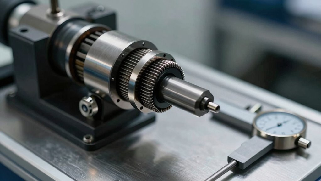
Torsional strain gauges are metallic-electrical measuring elements that detect this rotational force with exceptional precision, capturing twisting shear strain through changes in electrical resistance.
These specialised devices function by converting mechanical deformation into quantifiable data. When a shaft twists, the strategically positioned gauges experience strain, altering their electrical resistance proportionally. This resistance change, amplified through a Wheatstone bridge circuit, translates into accurate torque measurement readings. The zig-zag pattern etched onto the measuring grid enables extremely small dimensions for quasi point-like measurements of torque on rotating shafts.
For automotive professionals and engineers, torsional strain gauges deliver cutting-edge software solutions that integrate with dynamometer systems, providing critical perspectives into drivetrain efficiency, engine performance, and component integrity.
Their compact design, accuracy, and cost-effectiveness make them indispensable for anyone serious about comprehending vehicle behaviour and optimising performance across diverse testing applications.
Comprehending torsional strain gauges requires knowing how they capture the invisible twisting forces that flow through a vehicle’s drivetrain at the moment they occur.
When torque applies to a shaft, it creates pure shear stress that deforms the metal body. Strain gauges, oriented at 45 degrees to the shaft axis, detect this deformation by measuring resistance changes.
Four gauges form a Wheatstone bridge circuit, converting resistance variations into differential voltage proportional to torque. Different gauge types—such as 187UV shear patterns or 250US windmill patterns—suit specific torque applications.
This configuration enables real-time measurement with exceptional accuracy, allowing engineers and technicians to monitor drivetrain efficiency instantaneously and extract actionable performance data. Wireless RF powered torque modules accommodate vertical or lateral shaft movement while maintaining picostrain sensitivity for precise measurements across diverse industrial environments.
Invisible forces twist through every rotating shaft in a vehicle’s drivetrain, and grasping how these forces deform metal is essential to comprehending how torsional strain gauges function.
When torque is applied to a shaft, shear stress develops along the material’s cross-section, causing internal layers to slide relative to one another. This shear behaviour creates strain—a measurable deformation proportional to the applied stress. In structural engineering contexts, this same principle helps engineers assess the load-bearing capacity of critical components under demanding conditions.
The relationship between shear stress and strain follows Hooke’s law: τ = Gγ, where G represents the shear modulus, a material constant indicating rigidity. Steel, commonly used in drivetrain components, exhibits a shear modulus of approximately 80 GPa. Through advanced testing methodologies, engineers can validate these material properties and ensure components perform reliably under real-world conditions.
Hooke’s law governs shear stress and strain relationships: τ = Gγ, where shear modulus G quantifies material rigidity.
Recognising stress distribution across the shaft’s cross-section allows engineers to position strain gauges precisely, enabling accurate torque detection and real-time performance monitoring in demanding automotive applications.
Comprehending shear stress distribution across a shaft provides the foundation for torque measurement, yet detecting these minute deformations requires more than simply placing a single sensor on the material. A single strain gauge struggles with sensitivity and temperature compensation, limiting measurement precision.
The Wheatstone Bridge configuration alters this capability by strategically positioning multiple gauges to amplify resistance changes.
Bridge Configuration Benefits:
Full bridge configurations, with gauges positioned at 45-degree orientations, deliver superior torque detection through amplified differential voltage. The null deflection principle of the Wheatstone Bridge ensures that when the bridge is balanced, no current flows through the measurement circuit, allowing for precise detection of even minute resistance changes caused by torsional strain. Mastery of these measurement principles represents a critical component of operational mastery for professionals working with dynamometer technology.
This arrangement compensates for temperature fluctuations while minimising lead-wire resistance errors, establishing the gold standard for precision torque measurement in professional automotive diagnostics.
When a shaft experiences torsion, shear stress generates tensile and compressive stresses oriented at 45 degrees to the shaft’s axis, making proper gauge positioning critical for accurate measurement.
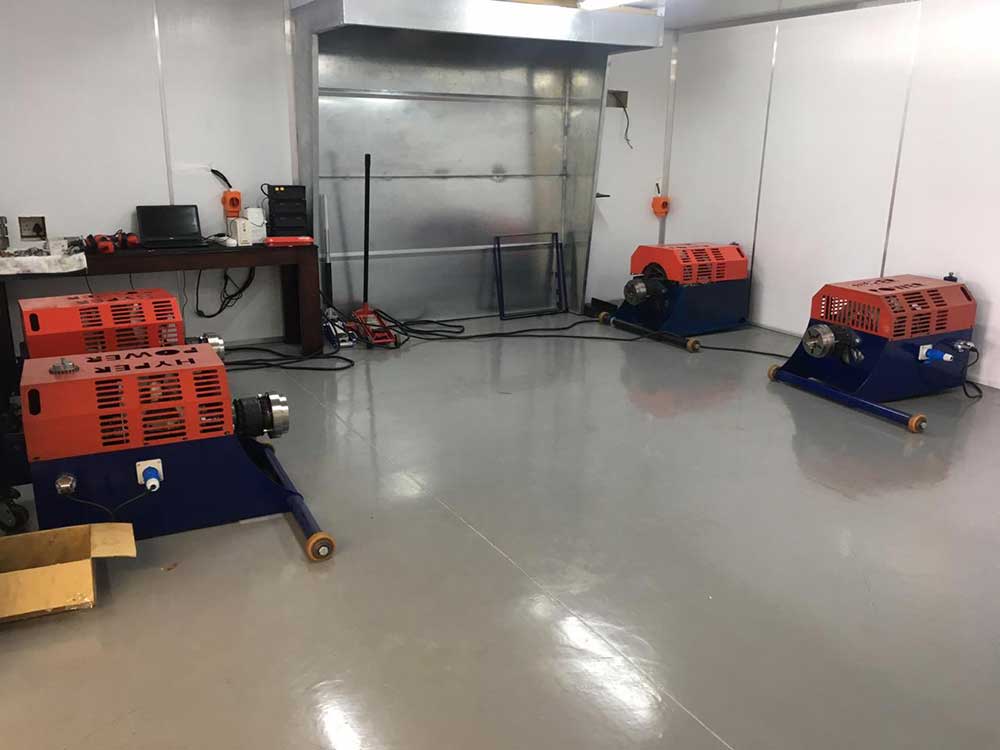
Strain gauges installed at this precise 45-degree angle capture these principal stresses while simultaneously isolating torsional strains from unwanted bending effects, ensuring the sensor reads pure torque rather than spurious signals. Full bridge configurations help compensate for parasitic effects like bending moments, with the output signal depending on gauge factor, strain level, and material’s Poisson’s ratio. At Hyper Power International, we emphasise the importance of precision testing services to validate your measurement systems before deployment.
Correct alignment during installation, guided by orientation marks and verified through careful surface preparation and bonding techniques, directly determines whether the measurement reflects genuine mechanical behaviour or introduces measurement errors that compromise data integrity.
At the heart of accurate torque measurement lies a fundamental principle: strain gauges positioned at 45-degree angles to a shaft’s axis capture the precise shear stresses that torsional loading produces.
When torque application occurs, maximum shear stress develops at 45 degrees to the principal stress directions. This stress distribution pattern is critical for reliable measurement. Gauges oriented at this angle sense the tensile and compressive stresses induced by torque, while excluding axial and bending effects that would compromise accuracy.
The detection mechanism operates through specific advantages:
This orientation guarantees that dynamometer systems, like those from Hyper Power, deliver scientifically valid, repeatable torque data across diverse testing applications. By leveraging real-time performance evaluations, engineers can continuously monitor strain gauge accuracy and make immediate adjustments to maintain measurement integrity throughout extended testing protocols.
The precision of torque measurement hinges entirely on proper strain gauge installation, which demands careful attention to angular positioning.
Correct 45-degree alignment marks on gauges prove essential for isolating torsional strains from unwanted bending effects. Gauge misalignment consequences can be severe, producing inaccurate readings that compromise entire testing protocols.
Installation techniques require thorough surface preparation, precise connection methods, and protective covering to maintain measurement integrity.
Weldable strain gauges positioned at 45 degrees maintain linear strain-resistance relationships up to 1000 × 10⁻⁶ strain.
Post-installation verification through insulation resistance testing, targeting over 20 megohms, confirms proper gauge functionality.
Partnering with technical support experts ensures your installation meets industry standards and maximises the long-term reliability of your measurement systems.
This careful approach prevents spurious signals and establishes the foundation for reliable torque data acquisition, enabling professionals to trust their dynamometer results completely.
Rotation speed and direction detection represents a critical capability in modern dynamometer systems, enabling precise monitoring of drivetrain behaviour under load.
Hyper Power’s advanced rotation sensing technology employs a sophisticated dual-sensor approach that delivers directional accuracy essential for thorough vehicle testing.
The system employs:
A magnet wheel with alternating poles and dual fixed sensors enable precise directional detection and speed measurement with 0.03-degree tolerance.
The time shift between sensor signals determines rotational speed with 0.03-degree tolerance, while phase-differentiated signal analysis distinguishes bidirectional rotation.
This configuration enables operators to capture precise performance data across varying load conditions, supporting both forward and reverse testing scenarios critical for thorough drivetrain analysis and optimisation. Professional installation and setup service ensures these advanced sensing systems are properly calibrated to deliver the accuracy your testing environment demands.
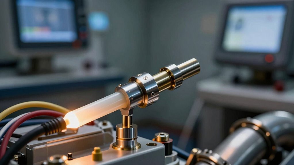
The fundamental challenge of extracting accurate torque data from a rotating shaft requires a reliable method to transmit measurement signals from the spinning element to stationary readout equipment, a task that engineers address through several distinct technological approaches.
Slip ring systems, which use conductive rings and brushes to transfer signals through direct contact, represent the traditional foundation for this transmission, while modern alternatives like magnet wheel detection systems and real-time signal processing methods offer improved performance characteristics suited to specific operational demands.
Comprehending the strengths and limitations of each transmission method enables engineers to select the most appropriate technology for their particular testing application, whether prioritising cost-effectiveness, measurement accuracy, or operational speed.
Selecting the right transmission method also ensures enhanced data collection and analysis capabilities that support both current testing requirements and future upgrades to dynamometer systems.
Imagine a dynamometer chassis measuring the power output of a high-performance engine, with sensors mounted directly on the rotating driveshaft collecting real-time data. Without slip rings, transmitting these critical signals would be impossible.
Slip rings enable continuous electrical contact between stationary brushes and rotating conductive rings, maintaining uninterrupted power and signal transmission regardless of rotation angle.
The technology relies on several key components working in concert:
Different slip ring types, including drum, pancake, and capsule designs, accommodate various space constraints and application requirements, making them indispensable for modern dynamometer systems. Advanced integration capabilities allow slip ring technology to seamlessly interface with custom dynamometer software for optimised signal transmission and data accuracy.
While slip rings provide one pathway for capturing signals from rotating components, magnetic wheel detection systems offer an alternative approach that eliminates the wear associated with brushes and conductive connections.
Magnet wheel integration employs Hall Effect sensors paired with strategically positioned magnets on rotating shafts, transmitting contactless speed and position measurement.
These magnetic sensing technologies operate through five distinct transmission modes: orthogonal, parallel, taper, end surface, and coaxial configurations. Each mode orients the magnetic field differently to accommodate specific shaft geometries and installation constraints.
Hall Effect sensors provide zero-wear operation with lifespans exceeding ten years, ideal for harsh dynamometer environments.
The DRV5033-Q1 variant enables fully enclosed sensing, ignoring contaminants while maintaining digital signal integrity above 20kHz bandwidth, ensuring accurate torque calculations in demanding testing scenarios.
Regular software updates enhance the accuracy and reliability of magnet wheel detection systems by refining signal processing algorithms and expanding compatibility with evolving dynamometer configurations.
Extracting meaningful data from a rotating shaft requires sophisticated transmission methods that convert physical motion into electronic signals, which Hyper Power’s dynamometer systems accomplish through multiple proven approaches.
The integration of advanced signal modulation techniques guarantees accurate torque measurements across diverse testing scenarios.
Key transmission capabilities include:
Sequential post-processing stages reconstruct sensor contributions after continuous signal evaluation, maintaining measurement integrity.
This framework allows professionals to capture precise torque data reliably, supporting confident performance analysis and optimisation decisions across dynamometer operations.
The critical role of strain gauge torque sensors extends across the entire automotive powertrain, from engine output shafts to transmission assemblies and motor drive systems.
In engines, flex plate torque sensors measure real-time output directly at the shaft, while active rotary sensors capture performance data during operation. These strain gauge applications enable precise torque measurement techniques essential for performance optimisation and fuel efficiency analysis.
Motor testing employs STS and RST Series sensors to monitor torque from electric motors and internal combustion engines, ensuring accurate control and reliability.
Gearbox evaluation employs both inline and reaction torque sensors to assess strain and transmission efficiency throughout the drivetrain. This thorough sensor integration supports quality assurance, horsepower verification, and powertrain calibration across industrial and automotive sectors.
When selecting between shear and beam stress designs, engineers must evaluate how each configuration responds to direct torsional loading, which fundamentally differs in sensitivity and measurement accuracy.
Beam deflection considerations become critical in applications where perpendicular forces interact with torsional loads, as the dual-gauge tension-compression arrangement can either improve or compromise torque readings depending on shaft geometry.
Material stiffness requirements vary greatly between designs, with shear gauges demanding rigid carrier substrates to maintain diagonal orientation integrity, while beam setups benefit from slightly flexible elements that allow controlled bending without permanent deformation.
Automotive dynamometers and torque testing systems rely on accurate shear stress measurement to capture the true mechanical behaviour of rotating components, particularly shafts and drive elements under operational loads.
Unlike beam stress designs that measure bending forces, direct shear applications demand 45° gauge orientations aligned precisely with torsional forces.
Key measurement advantages include:
This approach enables engineers to monitor power transmission under variable conditions with clinical precision, altering raw mechanical forces into actionable performance observations for vehicle optimisation.
Selecting between shear stress designs and beam stress designs represents a critical decision that fundamentally shapes measurement accuracy in dynamometer systems.
Shear stress designs employ strain gauge placement at 45-degree angles to detect torsional forces, while beam stress designs make use of multiple gauges on upper and lower surfaces for deflection measurement. Each approach offers distinct advantages depending on your testing requirements.
Beam stress configurations excel at capturing tensile and compressive strains simultaneously on opposite surfaces, providing thorough deflection data.
Shear stress designs deliver superior sensitivity for pure torsional applications. Proper alignment between stress direction and gauge orientation remains essential, as accuracy depends directly on positioning precision.
Grasping your specific load conditions guarantees ideal gauge selection and reliable performance data for your facility’s unique testing protocols.
The mechanical properties of a shaft or sensor housing directly determine how accurately strain gauges can measure torsional forces, making material selection a foundational consideration in dynamometer design.
High-stiffness materials prove essential for reliable torque measurement systems. When selecting materials and calibration techniques, engineers must prioritise resistance to deformation:
Zirconia’s 70–80 GPa shear modulus exemplifies ideal material selection for precision applications.
Shear gauge configurations on high-stiffness materials outperform beam designs by minimising mixed bending and axial strains, providing superior resolution and repeatability for professional automotive diagnostics and performance testing.
Because strain gauges operate at the intersection of material science and electrical measurement, the choices made during gauge selection and system calibration directly determine whether torque readings reflect reality or introduce systematic errors.
Material Compatibility and Gauge Selection
Selecting the correct alloy composition—such as copper-nickel or nickel-chromium foils—ensures the gauge responds predictably to torsional forces.
Correct alloy composition in copper-nickel or nickel-chromium foils ensures strain gauges respond predictably to torsional forces.
Self-compensated strain gauges matched to the test material’s thermal expansion coefficient eliminate temperature-induced measurement drift, particularly critical for steel, aluminium, and titanium applications.
Calibration Techniques for Accuracy
Proper calibration techniques reduce resistance changes caused by temperature fluctuations rather than actual strain.
Installation accuracy, including precise 45-degree alignment of shear grids and secure bonding, prevents directional errors.
When material compatibility and calibration techniques work together, bonded resistance strain gauges achieve accuracy better than ±0.10%.
South African workshop owners reject traditional banks. Dyno Finance proves faster funding exists—here’s what changes everything.
Most technicians miss critical factors that cause speed sensor failures. Learn what separates reliable diagnostics from cascading system problems.
Narrowband sensors are costing you power. Learn why wideband O2 technology separates real tuning from guesswork—and how to implement it correctly.
Your dyno numbers are incorrect. Temperature, humidity, and pressure quietly distort every measurement—correction factors reveal what your engine actually produces.

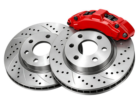
Heavy-duty fleets waste thousands on brake wear. One controller feature changes everything—here’s why most managers miss it.

Modern dyno testing exposes a hidden gap between leading DAQ platforms and the rest. What are you missing?

Hyperwin4 rewrites dyno tuning with AI diagnostics and real-time cloud power. But are your devices ready for this shift?
Master roller-to-hub conversion or watch your drivetrain fail. Learn the precision steps that separate reliability from costly mistakes.