Meta Description:
Engineers waste thousands on the wrong sensors every year. Torque transducers and load cells look similar but measure fundamentally different forces—and swapping them destroys accuracy. One spins, one stays still. Most teams get this backwards, silently ruining test results until it’s too late. Learn which sensor actually matches your demands before your next installation fails.
Force vs. Torque: What’s the Core Difference?
Although force and torque are both fundamental concepts in mechanics, they operate in distinctly different ways.
Force represents a push or pull that causes linear motion, calculated using the formula F = ma, where mass multiplies by acceleration.
Torque, conversely, is the rotational equivalent, requiring force applied at a distance from a rotation axis, expressed as τ = r × F × sin(θ).
Force applications produce straight-line acceleration independent of distance, depending solely on mass and acceleration magnitude.
Torque characteristics, however, depend on three factors: force magnitude, lever arm length, and the angle between them. Doubling the lever arm doubles torque output with identical force, while doubling mass halves acceleration with the same force applied.
Both are vector quantities possessing magnitude and direction, yet their effects differ fundamentally in motion production and measurement requirements. Torque is essential in rotational motion applications such as gears, doorknobs, and engine performance, demonstrating its critical role in mechanical systems.
When to Choose Load Cells: Static Force Applications
While comprehending the distinction between force and torque provides foundational knowledge, recognising which measurement tool suits a specific application proves equally important.
Load cells excel in static load applications where forces remain constant or change slowly over time. These devices employ strain gauge technology, which converts mechanical deformation into precise electrical signals without significant drift during prolonged measurements.
Load cells deliver superior performance in environments requiring long-term stability and minimal creep. Their sturdy construction withstands harsh industrial conditions while maintaining excellent repeatability and accuracy. Custom load cells offer enhanced accuracy and precision tailored to specific testing needs, improving the reliability of results in demanding industrial environments.
Applications span material testing laboratories, structural monitoring on bridges, automotive component crash assessments, and aerospace measurement procedures.
For professionals managing steady, non-rotational forces, load cells represent the best choice, offering cost-effective reliability that torque transducers cannot match in static scenarios.
When to Choose Torque Transducers: Rotation and Dynamic Forces
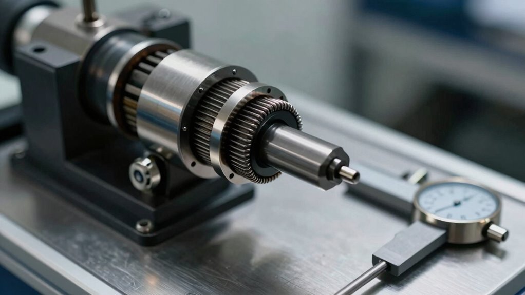
In applications involving rotating shafts, spinning components, and forces that change rapidly over time, torque transducers emerge as the measurement solution that load cells cannot provide. Unlike static devices, torque transducers excel at fluid measurement of forces occurring during engine operation, transmission testing, and electric motor evaluation.
These sensors deliver real-time torque monitoring with exceptional precision, measuring ripple effects up to 25 kHz using piezoelectric technology. They capture torsional oscillations and vibrations simultaneously, differentiating between mechanical phenomena that load cells miss entirely. The fixed installation position of these transducers ensures repeatable and reproducible measurement results across multiple testing cycles. Our cutting-edge software solutions continuously log and analyse this dynamic data for comprehensive performance insights.
With accuracy below 0.5% and operating ranges spanning -45°C to 150°C, torque transducers handle demanding automotive environments where rotating components demand continuous, reliable data acquisition for performance optimisation.
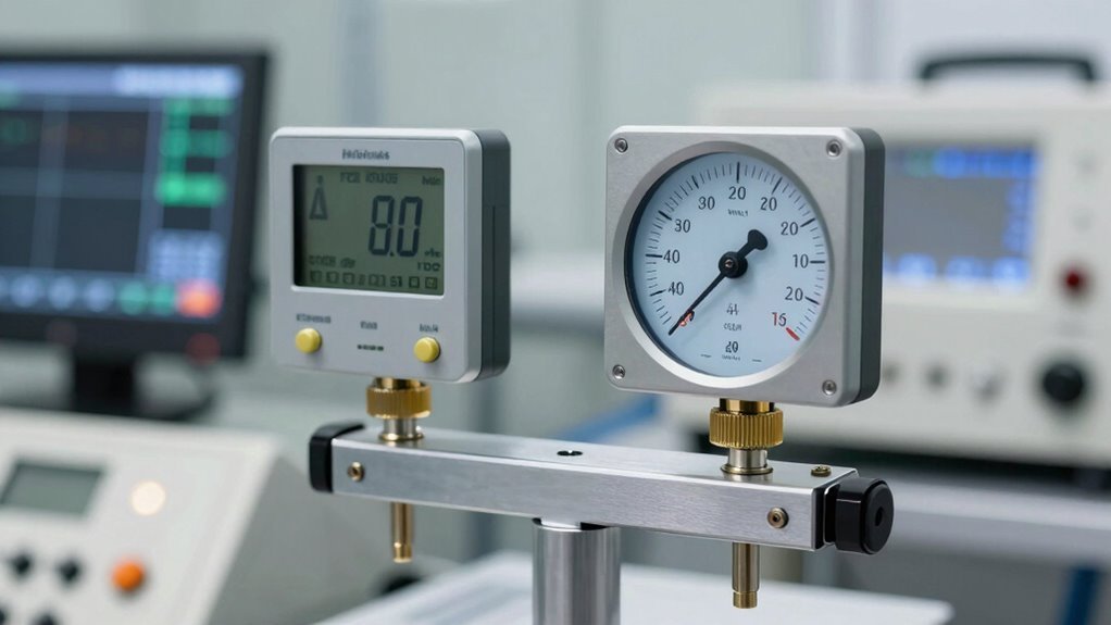
Comparing Accuracy, Response Time, and Environmental Durability
Beyond their ability to capture energetic rotational forces, torque transducers and load cells must prove themselves in three critical performance dimensions: measurement accuracy, signal response speed, and long-term durability in harsh conditions.
| Performance Metric |
Torque Transducers |
Load Cells |
| Accuracy Range |
0.03–0.25% of capacity |
0.03–0.25% of capacity |
| Response Technology |
Strain gauge with telemetry |
Strain gauge direct signal |
| Environmental Durability |
100M cycles, torsion-resistant |
100M cycles, fatigue-resistant |
| Calibration Interval |
Annual verification required |
Annual verification required |
Both sensor types deliver comparable accuracy comparison results through strain gauge technology. Response time favours rotating transducers using contactless telemetry, eliminating cable delays. Load cells sense minute force changes faster than alternative technologies. Both withstand 100 million fully reversed cycles in demanding environments, requiring annual calibration to maintain performance specifications and guarantee measurement reliability. Selecting the appropriate sensor technology depends on your specific testing objectives and the advanced testing methodologies you plan to implement. For multi-sensor installations, a load cell summing box becomes essential to combine signals from each transducer into a single coherent output.
Capacity, Overload Protection, and Budget Alignment
Selecting the right capacity for torque transducers and load cells requires balancing measurement accuracy, protection against unexpected peak loads, and overall system costs.
Oversizing sensors reduces measurement resolution and increases expenses, while undersizing creates vulnerability to damage during transient events like engine startup or impact loading. Wheatstone bridge circuits within load cells detect small changes in resistance from strain gauges, enabling precise force measurement that becomes compromised when sensors are oversized beyond application requirements.
Hyper Power International’s commitment to precision testing services ensures that organisations select equipment calibrated for their specific performance requirements. Comprehending these trade-offs enables organisations to invest strategically in equipment that delivers reliable performance without unnecessary financial waste.
Capacity Matching and Resolution Trade-offs
Because torque transducers and load cells operate under fundamentally different physical principles, their capacity ranges and measurement characteristics deviate in ways that directly impact equipment selection and testing accuracy.
Capacity Considerations and Resolution Trade-offs
Selecting the correct capacity requires matching sensor specifications to actual operating conditions. Load cells handle broad force ranges efficiently, while torque sensors excel at twist-specific movement.
Oversizing either reduces sensitivity and wastes budget; undersizing risks sensor damage and invalidates data.
Higher capacity torque transducers increase weight and limit maximum RPM, creating fundamental trade-offs. Resolution suffers when capacity exceeds actual requirements, sacrificing precision for unnecessary headroom.
Professional testing demands that capacity align precisely with expected peak loads, including transients, ensuring both measurement accuracy and equipment longevity within budget constraints. Hyper Power’s proactive system monitoring helps identify optimal sensor specifications before deployment, preventing costly capacity mismatches.
Overload Protection Mechanisms and Costs
Precision in capacity selection sets the foundation for reliable measurements, yet even properly sized sensors face moments when loads spike beyond their rated range. Overload mechanisms protect against damage while maintaining long-term accuracy and cost efficiency.
Professional engineers employ several proven protection strategies:
- Mechanical stops in load cells limit deflection at rated capacity, preventing permanent strain without calibration loss.
- Torque transducers use geared backlash elimination, shifting excess load to secondary axles while maintaining measurement precision.
- Friction torque limiters slip at preset thresholds, protecting equipment like conveyors without requiring electronic complexity.
These mechanical solutions offer distinct advantages. Tolerance rings provide low-cost assembly with minimal weight penalties, while integrated overload features prevent expensive replacements.
Retrofit limiters extend equipment life without major infrastructure modifications, producing measurable value across diverse applications. Expert calibration techniques employed during professional installation ensure that overload protection mechanisms function optimally throughout the dynamometer’s operational lifespan.
Budget Constraints and Long-term Value
When organisations evaluate torque transducers and load cells, the initial purchase price often obscures a more complex financial depiction that extends well beyond the invoice date.
A cost benefit analysis reveals that durable materials—copper alloy slip rings, aluminium construction, and strain gauge designs—reduce long-term replacement expenses considerably.
Investment longevity improves markedly when selecting temperature-compensated models like the MBA500, which sustains performance across tension, compression, and torque applications over extended periods.
Stainless steel variants offer overload resistance up to 0.3mm at 6Nm torque, minimising costly rework.
Custom configurations matching specific capacity requirements enhance budgets while ensuring reliability, and quality assurance processes throughout the product lifecycle guarantee sustained performance and cost-effectiveness.
Organisations aligning load cell specifications to operational demands achieve superior value, balancing quality, cost, and delivery timelines effectively.
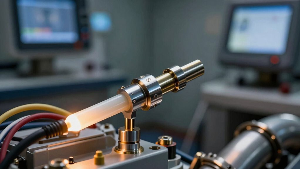
Signal Transmission: How Stationary vs. Rotary Sensors Communicate
The fundamental difference between stationary and rotary torque sensors lies in how they transmit electrical signals from the measurement point to the data acquisition system. Stationary sensors rely on direct wiring connections, while rotating systems employ advanced contactless technologies to maintain signal integrity during operation.
Key transmission methods include:
- Stationary sensors use direct electrical connections between strain gauges and external conditioning equipment, requiring wired signal pathways.
- Rotary converters enable contactless voltage transmission through magnetic flux patterns, eliminating cable confusion without sacrificing transmission efficiency.
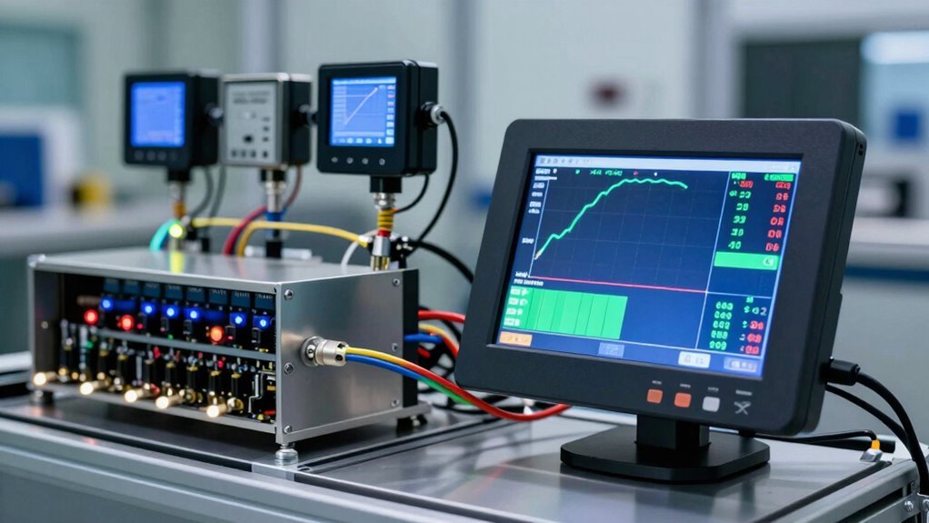
- Onboard electronics in rotating systems amplify and digitise signals before transfer, reducing external equipment dependencies.
Each approach balances practicality with measurement precision, determining suitability for specific automotive testing applications and operational environments. Implementing real-time data collection during dynamometer testing processes ensures that signal transmission methods deliver the accuracy and reliability required for comprehensive performance analysis.
Shaft Type, Mounting, and Zero-Backlash Setup
Once electrical signals travel reliably from the measurement point to the data acquisition system, the next critical consideration becomes how torque actually enters the sensor itself.
Shaft Configurations and Their Role
Solid circular shafts represent the standard approach, offering uniform torque introduction with zero backlash. Hollow circular alternatives suit rotating applications, while solid square shafts excel in high-capacity scenarios exceeding 500 in-lb.
Solid circular shafts deliver uniform torque introduction with zero backlash, while solid square shafts excel in high-capacity applications exceeding 500 in-lb.
Keyed shafts provide secure coupling options, though they demand interference fits through heating or pressing to prevent wear-related backlash.
Mounting Techniques and Sensor Alignment
Proper mounting techniques directly influence measurement accuracy. Foot-mounted housings require double-flex couplings to accommodate angular and parallel misalignment.
Flange-style sensors offer compact designs for space-constrained setups, while shaft couplings reduce bending effects by supporting coupling weight. Advanced integration capabilities enhance overall dynamometer performance when sensors are properly aligned with existing measurement systems.
Backlash Prevention Strategies
Zero-backlash setups employ smooth shafts with shrink-disk hubs or split collars, ensuring precise readings in demanding applications.
Installation, Calibration, and Testing for Accuracy
Proper installation serves as the foundation for reliable torque and force measurement, determining whether sensors deliver the precision required for valid testing results. Strategic installation methods and calibration techniques work together to guarantee sensors function at their best within dynamometer systems.
Key Installation and Calibration Practices:
- Four-arm Wheatstone bridge configurations compensate for temperature fluctuations and cancel non-axial forces, maintaining consistent output accuracy across varying environmental conditions.
- Regulated 5-20 V DC excitation is applied across bridges, generating output voltage proportional to applied load or torque for precise data acquisition.
- Capacity selection balances resolution against overload risk; undersized sensors risk damage while oversized units reduce measurement accuracy.
Proper zero-load balancing establishes baseline signals before testing begins.
These calibration techniques, combined with careful installation protocols, enable professionals to extract maximum reliability from their measurement systems, supporting confident decision-making during performance analysis. Regular software updates further enhance sensor accuracy and system performance capabilities.
Real-World Examples: Selecting the Right Sensor for Your Industry
With installation and calibration fundamentals in place, professionals must now match sensor technology to their specific operational demands.
The automotive sector relies heavily on torque transducers for engine dynamometers, measuring power output with precision. Load cells excel in structural testing, handling tension and compression forces across vehicle components.
Aerospace applications demand fatigue-rated sensors capable of resisting millions of cycles during flight simulations.
Industrial automation benefits from THD Series load cells in robotic assembly, ensuring consistent quality control.
Materials testing laboratories depend on THB and THC Series units for evaluating metal, plastic, and composite properties.
Selecting the appropriate sensor requires comprehension of both industry standards and specific measurement requirements, ensuring data reliability and operational efficiency across diverse applications. Pursuing professional certification in sensor technology provides the expertise needed to make informed decisions across these specialised fields.