Industrial Dyno Testing: Why Most Manufacturers Get It Wrong
Most engine manufacturers believe their lab testing protocols are sufficient—until their equipment fails in the field. Industrial dyno testing separates the pretenders from the genuine innovators by exposing operational weaknesses that standard assessments miss entirely. The right dynamometer choice, testing approach, and data analysis can mean the difference between a market leader and a costly recall. Discover what separates industry titans from their struggling competitors.
What Is Industrial Dyno Testing and Why It Matters
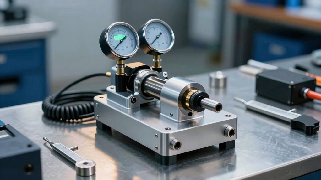
A dynamometer—or dyno, as industry professionals call it—is a precision instrument that measures the torque, rotational speed, and power output of engines, motors, and other mechanical devices under controlled laboratory conditions.
These systems eliminate unpredictable variables present in field testing, allowing engineers to capture critical performance metrics with clinical accuracy.
Industrial applications span automotive, aerospace, manufacturing, and energy sectors. Dyno testing verifies equipment quality before implementation, identifies weaknesses that only surface under load, and guarantees operational safety. Fine-tuning of engine parameters maximises both performance and efficiency across diverse industrial applications. State-of-the-art testing facilities ensure precise and insightful results through comprehensive data collection across a range of conditions.
By subjecting engines and motors to systematic load application, facilities detect overheating issues, sensor malfunctions, and performance anomalies early.
This controlled testing approach prevents costly post-implementation failures, reduces warranty claims, and instils customer confidence through documented results.
In-house dynamometer facilities provide full control over testing quality and expediency, making them essential strategic investments for manufacturers and service technicians alike.
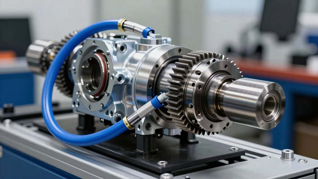
Choose Your Dynamometer: Engine, Eddy-Current, Water Brake, or AC
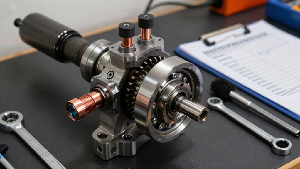
Engine dynamometers measure torque and rotational speed directly from the engine output shaft, making them ideal for applications ranging from street engines to high-performance race cars. Though they require careful consideration of the specific dyno type—inertia, brake, or eddy current—based on testing needs.
Eddy-current dynamometers deliver precise load control with rapid response rates, offering ±0.5% accuracy at the cost of a narrower operational range and higher initial expense compared to water brake alternatives. Our cutting-edge software solutions ensure seamless integration with these advanced systems for optimal performance measurement.
Water brake systems provide economical broad-range testing capability, handling everything from small engines under 40 lb.ft to large applications at 1,250 lb.ft torque. Though they demand more frequent maintenance due to water circuit scaling and slower transient response. Electric dynamometers excel in simulating transient conditions with superior accuracy and extended operational lifespan beyond 10 years.
Engine Dyno Direct Measurement
Direct measurement of engine output represents the most accurate approach to evaluating vehicle performance, efficiency, and durability in controlled laboratory conditions.
Engine dynamometers connect directly to the engine’s output shaft, eliminating drivetrain losses that compromise chassis dyno readings. This direct connection enables precise engine calibration and performance measurement with clinical accuracy. Hyper Power International’s commitment to precision and reliability ensures that testing equipment meets the highest industry standards for accurate results.
Engine dynos excel where precision matters most:
- Eliminating drivetrain variability that skews real-world data
- Achieving repeatable results across identical testing protocols
- Supporting detailed engine calibration before vehicle integration
Classified as either power absorption or transmission types, engine dynamometers measure torque and RPM to calculate horsepower under controlled conditions. Brake dynamometers maintain constant speed while applying variable load to provide detailed performance data for tuning and optimisation.
Eddy-Current Precision And Cost
Eddy-current dynamometers represent a versatile middle ground in the dynamometer hierarchy, providing precision torque measurement without the complexity or maintenance demands of hydraulic alternatives.
These systems utilise electromagnetic principles, generating opposing forces through eddy currents within rotating conductors placed in magnetic fields.
The precision reaches ±0.5% full-scale accuracy via strain gauge load cells, enabling reliable torque and speed measurements across diverse testing protocols.
Cost optimisation becomes evident through minimal power consumption, durable nickel-plated components resisting cooling water corrosion, and pre-lubricated bearings requiring servicing only after 5,000 hours. These durable components are specifically designed to withstand demanding environments while maintaining consistent performance over extended operational periods. The quality assurance processes ensure that all components meet stringent manufacturing standards before deployment in demanding testing environments.
Eddy current efficiency shines in versatile configurations, accommodating testing needs from 80 kW to 900 kW without requiring multiple units.
Maintenance-free operation compared to hydraulic systems further reduces long-term expenses, making these dynamometers ideal for professional workshops seeking industrial-grade performance at sustainable costs.
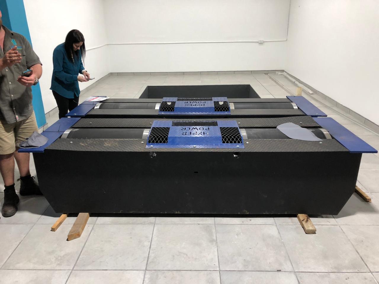
Water Brake Value Comparison
When selecting the ideal dynamometer for rigorous industrial testing, water brake systems present an intriguing alternative that merits serious consideration alongside eddy-current and AC solutions.
Water brake efficiency outperforms competing technologies through superior heat absorption and load capacity. These systems measure horsepower by calculating BTU output from thermal exchange, providing physics-based accuracy unmatched by other braking methods.
Why water brake dynamometer comparisons favour this technology:
- Handles up to 10,000 HP with exceptional torque capability at low speeds
- Dissipates largest heat amounts, essential for demanding industrial applications
- Functions across petrol, diesel, CNG engines, and AC motors without limitation
Water brakes excel where eddy-current systems falter. Their sturdy construction and straightforward operating principle create reliable, repeatable measurements. The rotor and stator pockets work together to accelerate water through the system, enabling thermal exchange measurements that correlate directly to engine power output.
Industrial professionals increasingly recognise water brake systems as the strategic choice for power generation testing environments requiring maximum dependability and performance understanding. Expert calibration techniques ensure that water brake dynamometers deliver the precision measurements necessary for accurate industrial testing and validation.
Budget, Speed, and Range: Which System Fits Your Needs?
How does one choose between dynamometer technologies when each offers distinct advantages in cost, performance, and capability?
Dynamometer selection requires balancing three critical factors: initial investment, response speed, and operational range.
Water brake systems deliver the lowest cost while handling any horsepower across broad test types, making them ideal for general testing with versatile requirements.
Electric dynamometers command a 40-60% premium pricing but provide millisecond-level response and ±0.2% control accuracy, essential for transient simulation and R&D applications.
Eddy current units occupy a specialised niche, offering rapid load adjustment despite similar cost premiums and narrow adjustable range.
Testing efficiency improves when matching technology to specific needs rather than pursuing one-size-fits-all solutions, ensuring peak performance within budget constraints.
Custom software solutions can further enhance testing precision by tailoring dynamometer systems to your unique vehicle configurations and specialised testing requirements.
Steady-State vs. Transient Testing: When to Use Each
Dynamometer testing divides into two fundamentally different approaches, each suited to distinct objectives and constraints.
Steady-state testing holds engines at constant speed and torque, providing rapid results with lower computational costs. Transient testing varies speed and load continuously, simulating real-world conditions with greater intricacy.
When Steady State Advantages Matter:
- Design optimisation phases requiring fast iterations and preliminary performance evaluation
- Quick analysis when time-dependent effects remain minimal to project success
- Budget-conscious operations needing efficient preliminary guidance without extensive computational demands
Transient intricacies demand longer runtime and specialised AC dynamometer capability, yet prove essential for emissions certification and component durability assessment.
Professional tuning workshops and race teams utilise steady-state methods for baseline enhancement, then employ transient testing for final validation. Hyper Power’s proactive system monitoring capabilities ensure your facility maintains optimal performance regardless of testing methodology chosen.
Comprehending your testing objectives determines which approach maximises both efficiency and accuracy for your facility’s specific needs.
The Six Core Components Every Test Cell Requires
Once a facility has established whether steady-state or transient testing serves its primary objectives, the next step involves building the physical infrastructure to support reliable, safe, and accurate dynamometer operations.
A properly designed test cell requires six foundational components. The structural foundation begins with concrete sub-bases and sound-insulated wall panels rated STC 50 or higher, ensuring noise control during high-RPM testing.
Ventilation systems with integrated silencers prevent carbon monoxide accumulation while maintaining accurate data integrity. Fuel infrastructure, including UL-142 double-wall tanks and delivery systems, supplies controlled fuel to test engines.
Coolant systems with heat exchangers manage thermal conditions. Electrical systems feature GFCI outlets and uninterruptible power supplies protecting sensitive equipment.
Finally, safety monitoring includes carbon monoxide detectors, fire suppression, and exhaust extraction systems. These interconnected components create the backbone of professional test cell design, enabling consistent performance measurement across diverse testing protocols. Pairing your test cell infrastructure with comprehensive technical support ensures your dynamometer systems operate at peak performance throughout their service life.
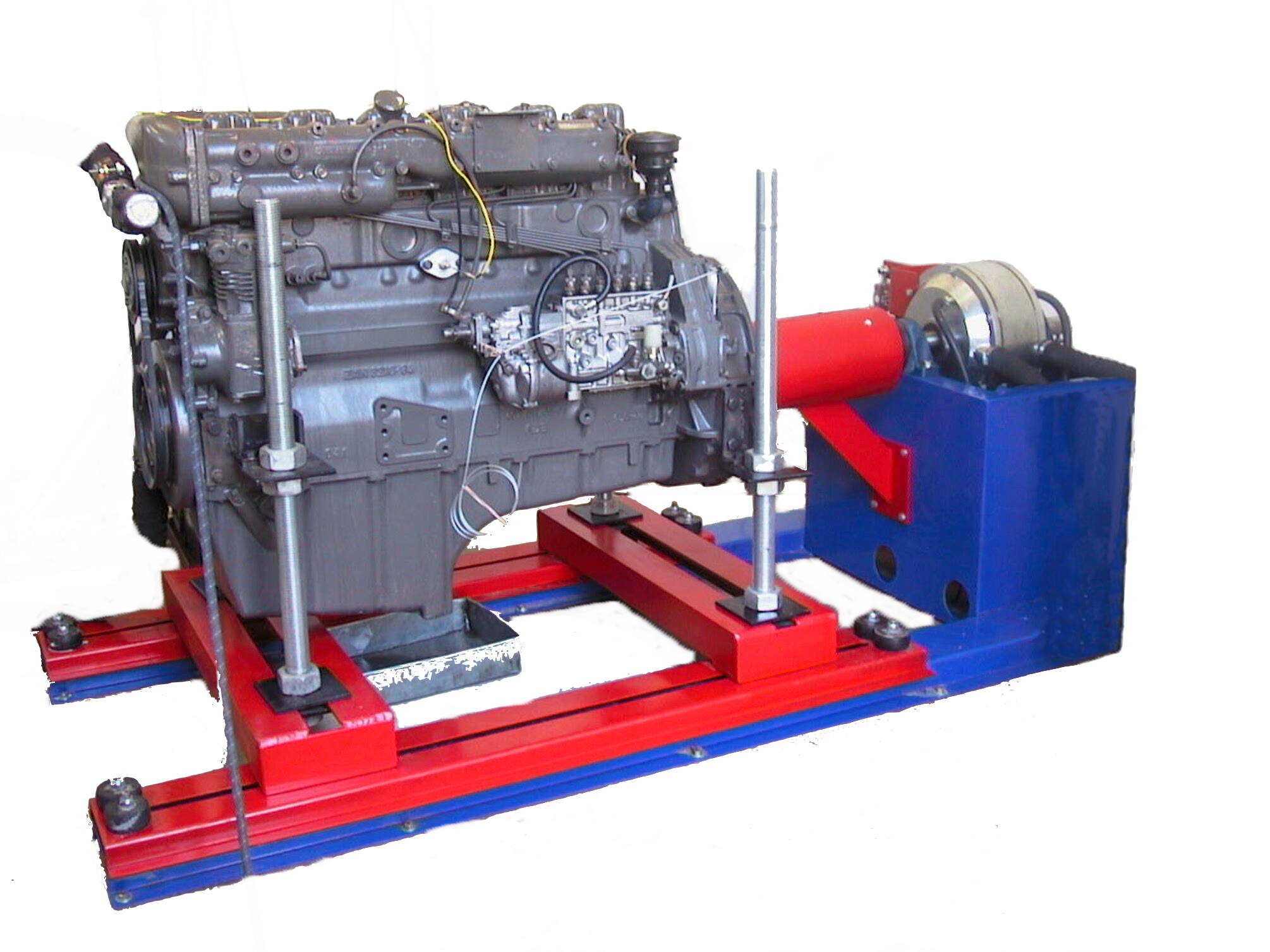
Testing Diesel, Gasoline, and Electric Motors: Key Differences
The engine type under test fundamentally determines which dynamometer system, testing methodology, and performance metrics best serve the evaluation objectives.
Diesel Motor Excellence
Diesel engines demand specialised water brake dynos designed for high diesel torque applications, ranging from 100 to 4,500 HP at speeds up to 4,000 RPM.
Specialised water brake dynos handle diesel torque applications from 100 to 4,500 HP at speeds reaching 4,000 RPM.
These systems excel in mining, construction, and marine sectors where strong torque provision matters most.
Petrol Efficiency Focus
Petrol motors benefit from eddy current brakes, providing superior petrol efficiency measurements through steady-state chassis dynos.
Load cell calibration guarantees accurate horsepower readings across performance testing scenarios.
Electric Responsiveness
Electric dynos provide unmatched testing accuracy at ±0.2% with millisecond response times, supporting power verification and transient conditions.
Key Distinctions
- Diesel prioritises torque measurement under sustained load
- Petrol requires precision efficiency tracking across RPM ranges
- Electric demands millisecond responsiveness for acceleration testing
Professional certification programmes ensure operators understand these critical distinctions and can select appropriate dynamometer systems for their specific testing requirements.
Most vehicles operate across dramatically different environmental conditions, yet many performance tests occur only under ideal laboratory settings. Cold weather testing and heat performance validation reveal how engines, motors, and drivetrains truly perform when pushed to environmental extremes.
Hyper Power’s thermal cycling chambers operate across -90°C to +240°C ranges, enabling engineers to simulate real-world conditions.
Altitude simulation equipment replicates sea level through 14,000-foot elevations, controlling combustion air temperature and pressure simultaneously.
Advanced cooling systems maintain motor temperatures between -40°C to 100°C during tolerance testing, while discharge water management prevents impurity buildup that reduces load capacity.
These capabilities guarantee vehicles meet performance standards across climates, from arctic regions to desert environments, providing reliable data that validates engineering excellence. Real-time performance evaluations during extreme condition testing ensure comprehensive assessment of vehicle reliability across all operating environments.
Inspection Checklists That Prevent Equipment Failure and Injury
Before any vehicle enters a dynamometer cell, thorough inspection protocols must verify that both the test equipment and the subject vehicle meet strict safety and operational standards.
These checklists address three critical dimensions: confirming pre-test safety conditions, evaluating the overall mechanical integrity of the equipment being tested, and identifying potential operational risks that could compromise results or endanger personnel.
Pre-Test Safety Verification
Every dynamometer testing session begins with a critical foundation: thorough pre-test safety verification that protects both personnel and equipment. A detailed pre-test checklist guarantees all systems function properly before any vehicle enters the test cell.
Operators must verify several essential conditions:
- All mechanical components are secure, undamaged, and properly calibrated to prevent catastrophic failures.
- Cooling system hoses and clamps remain tight, with no deterioration that could cause leaks or overheating.
- Fuel lines, fittings, and exhaust systems are leak-free to eliminate fire hazards.
These safety protocols form the foundation of responsible testing. Inspecting air filters, checking for weep hole leakage, and confirming intake seals prevents equipment damage.
This methodical approach allows technicians to identify potential problems early, guaranteeing safe operations and reliable test data for every session.
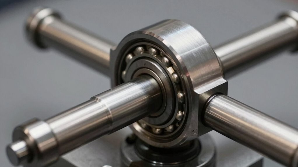
Equipment Condition Assessment Protocol
Systematic inspection checklists form the backbone of safe, reliable dynamometer operations, protecting both personnel and expensive testing equipment from preventable failures. Regular equipment health evaluations identify potential issues before they escalate into costly breakdowns or safety hazards.
Core Inspection Elements
Verification of component security and fastener integrity prevents mechanical failures during high-speed testing cycles. Visual damage assessment reveals structural compromises that could undermine safety or test validity. Calibration checks guarantee measurement accuracy, confirming that torque, power, and efficiency data remain scientifically valid.
Maintenance Strategies
Comprehensive maintenance strategies include filter condition monitoring, water pump inspection, and service component tracking with exact manufacturer part numbers.
Documentation systems record maintenance history and performance metrics, establishing baselines for trend analysis. These preventive approaches reduce downtime and extend asset longevity, guaranteeing consistent testing capability.
Operational Risk Mitigation Strategies
How can operators confidently protect both personnel and essential equipment during dynamometer testing? Extensive risk assessment and hazard identification form the foundation of safe operations, enabling teams to anticipate and prevent costly failures and injuries.
Essential Protective Measures:
- Implement automated safety limits that stop tests immediately when anomalies occur, protecting both operators and machinery.
- Perform thorough pre-operational inspections using detailed hazard checklists to identify electrical, noise, and moving part risks.
- Require mandatory PPE compliance during engine connection and testing phases, reducing injury exposure considerably.
Systematic maintenance protocols, including Lockout-Tagout procedures during servicing, guarantee equipment reliability.
Regular calibration verification and documented service logs maintain peak dynamometer condition.
Training programmes educate technicians on hazard recognition and CO poisoning prevention.
Organisations implementing risk management software reduce injury rates dramatically, creating safer testing environments where skilled professionals thrive confidently.
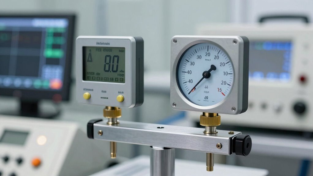
Reading Your Dyno Results: What the Numbers Mean
A dynamometer produces raw data—numbers that tell a precise story about engine performance, but only when properly interpreted. Comprehending dyno terminology clarification alters confusing readings into actionable observations about your engine’s capabilities.
Observed power and torque represent uncorrected measurements taken under current atmospheric conditions. These baseline figures vary greatly with temperature, humidity, and barometric pressure, making direct comparisons between test days unreliable without standardisation.
Power correction factors standardise results to SAE baseline conditions, enabling fair performance assessment across different testing environments. A correction factor of 1.066, for example, adds 6.6% to observed numbers for true comparability.
Most professional dyno sheets clearly indicate the percentage of correction applied, ensuring transparency and consistency in your performance evaluation.
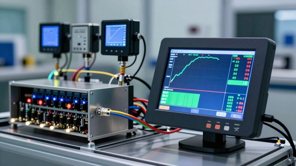
Turning Data Into Design Improvements
Once baseline performance metrics have been established and corrected for environmental variables, the real value of dynamometer testing emerges: the ability to identify specific areas where design and tuning adjustments can reveal measurable improvements.
Data interpretation alters raw numbers into actionable perspectives. Engineers examine torque curves, power outputs, and efficiency ratios to pinpoint performance gaps. This systematic approach enables targeted improvements rather than guesswork.
Design enhancement applications include:
- Adjusting winding configurations and magnet placement for improved power delivery
- Modifying cooling systems to maintain ideal thermal performance under load
- Evaluating structural components like carbon fibre retention under extreme conditions
The partnership between thorough testing and repeated design creates measurable performance gains, equipping engineers to push limits while maintaining reliability and safety standards.