Most professionals get torque wrong—and it’s costing them. Three deceptively simple variables control rotational force, yet their interaction remains widely misapplied across industries. When calculated incorrectly, the consequences ripple through equipment performance, safety protocols, and asset lifespan. Your current approach to torque measurement might be introducing hidden inefficiencies into every operation. Learn what the variables actually demand and why your competitors may already know this.
What Is Torque and Why Does It Matter?
Rotation, twist, and the mechanical forces that produce them form the foundation of modern machinery. Torque represents the rotational equivalent of linear force, measured in newton-metres, and describes how force causes objects to rotate around an axis.
Unlike simple pushing or pulling, torque twists or rotates, depending on the perpendicular distance from the rotation point.
Understanding torque applications proves essential across industries. Engines generate torque to accelerate vehicles from standstill, while trucks rely on torque to move heavy loads. The torque benefits extend to everyday tools like screws and hinges, making rotation possible throughout modern technology. Positive torque indicates counterclockwise rotation, while negative torque produces clockwise rotation depending on force direction.
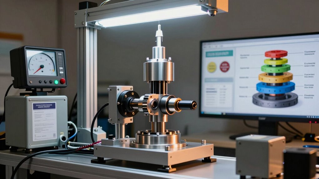
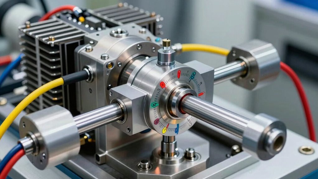
Torque’s magnitude and direction determine rotational acceleration, producing change in angular velocity. Professionals measuring vehicle performance recognise that torque directly correlates to mechanical capability and efficiency, making precise measurement critical for optimisation and reliability. For accurate torque measurement across diverse applications, dynamometer technology provides the precision and reliability necessary to optimise performance testing.
The mathematical foundation of torque reveals itself through a deceptively simple equation: T = F × R × Sinθ. This formula breaks down into three essential components that define all torque applications across automotive diagnostics and mechanical systems.
The torque equation T = F × R × Sinθ reveals three essential components defining all mechanical rotational applications.
The force (F) represents the applied push or pull, measured in newtons. The radius (R) indicates the distance from the pivot point to where force applies. The sine factor (Sinθ) captures the angle between force and lever arm, accounting for the perpendicular component that actually generates rotation.
Maximum torque occurs at 90 degrees, where sinθ equals one. At zero or 180 degrees, sinθ becomes zero, producing no rotational effect. Understanding that torque is a vector quantity with both magnitude and direction proves essential for proper rotational force analysis. Precision testing with advanced dynamometer systems ensures accurate measurement across all vehicle types and engine configurations.
Comprehending this relationship proves critical for accurate torque measurement in professional workshop environments, ensuring operators extract maximum value from advanced dynamometer systems.
How Lever Arm Distance Amplifies Rotational Force
While comprehending that maximum torque occurs when force meets the lever arm at a perfect 90-degree angle, operators must now grasp how distance itself becomes a powerful multiplier of rotational force.
Lever arm mechanics reveal that doubling the distance from the axis of rotation doubles the torque produced, regardless of force magnitude. This principle explains why a wrench generates a greater rotational effect when force is applied farther from the fastener. The perpendicular distance from the axis of rotation fundamentally determines the effectiveness of any applied force in creating rotational motion.
Professional technicians utilise this awareness in torque applications, calculating required forces based on available distances. A 200-newton force at three metres produces 600 newton-metres of torque, demonstrating distance’s amplification effect. Access to advanced testing methodologies enables precise measurement and validation of these torque calculations across diverse applications.
Grasping this relationship enables engineers and operators to enhance equipment performance, ensuring precise control across diverse testing scenarios and mechanical systems.
Torque Direction: Clockwise vs. Anticlockwise
Grasping torque direction requires recognising that rotation can occur in two opposing ways—clockwise or anticlockwise—and that physics uses specific sign conventions to distinguish between them.
The right-hand rule provides a practical method for determining which direction a torque acts, eliminating guesswork by converting spatial relationships into consistent, predictable results. Anticlockwise rotation is associated with positive torque, while clockwise rotation carries a negative value in standard physics calculations.
Commanding these concepts enables engineers and technicians to accurately predict rotational behaviour, ensuring systems remain balanced and operate as intended.
Right-Hand Rule Application
Determining torque direction requires a systematic approach that engineers and technicians rely on across all rotational systems, from dynamometer testing to industrial machinery operation. The right-hand rule provides consistency in vector analysis, translating three-dimensional force relationships into predictable rotational outcomes. By positioning fingers at the axis, pointing towards the force application point, and curling them in the force direction, technicians extend their thumb perpendicular to reveal the torque vector’s orientation. This method eliminates ambiguity in torque applications across professional settings. Advanced diagnostic tools now integrate torque direction analysis with real-time performance evaluations to enhance precision in testing protocols. Understanding that torque produces angular acceleration ensures that the direction determined by the right-hand rule directly corresponds to the direction of resulting rotational motion in the system.
| Step |
Action |
| 1 |
Position fingers at rotation axis |
| 2 |
Point fingers towards force location |
| 3 |
Curl fingers in force direction |
| 4 |
Extend thumb perpendicular |
| 5 |
Thumb indicates torque vector |
The thumb’s direction—pointing outward or inward—determines whether rotation proceeds counterclockwise or clockwise, establishing the torque’s sign convention.
Rotational Sign Conventions
Once the right-hand rule establishes torque direction, the next step involves assigning consistent numerical values to rotational motion. The standard sign convention designates counterclockwise rotation as positive and clockwise rotation as negative, though the choice of viewpoint fundamentally affects this assignment.
Engineers must specify their reference axis before applying signs to torque units, ensuring consistency across all torque diagrams and calculations. A chosen positive axis determines whether a force produces positive or negative torque; reversing the viewpoint reverses the sign.
This systematic approach prevents calculation errors and enables precise communication among professionals. By documenting sign conventions in all analyses and drawings, teams maintain clarity throughout complex torque chains, supporting safer design decisions and accurate performance predictions in dynamometer testing and automotive applications.
Torque manifests differently across automotive engines and hand tools, yet both applications rely on precise measurement to guarantee peak performance and safety.
In engines, torque directly influences vehicle acceleration and powertrain efficiency, making accurate quantification essential for tuning and diagnostics.
Hand tools, by contrast, require torque measurement to prevent fastener over-tightening and guarantee structural integrity across mechanical assemblies.
Professional certification in dynamometer technology ensures technicians possess the expertise to measure and analyse torque with precision across both applications.
Engine Torque and Vehicle Acceleration
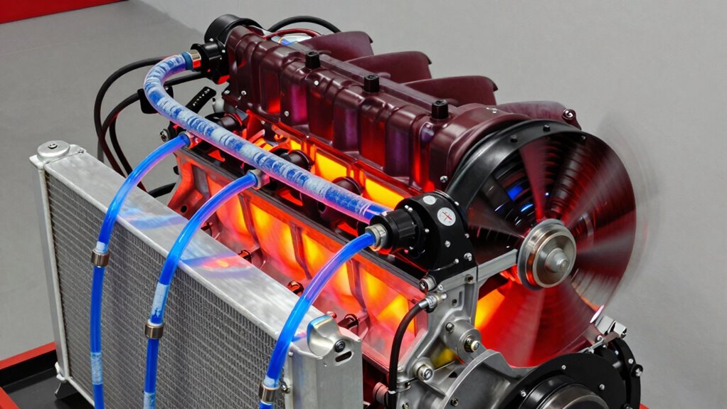
Every time an internal combustion engine fires, a precisely orchestrated sequence of events unfolds within its cylinders, converting chemical energy into mechanical force that drives vehicles forward.
Comprehending how engine torque translates into vehicle acceleration reveals the critical relationship between rotational force and real-world performance.
Torque delivery directly impacts acceleration capability through several interconnected mechanisms:
- High torque at lower RPMs enables quicker acceleration from a standstill, providing immediate responsiveness.
- Transmission gearing magnifies engine torque before force reaches the wheels, multiplying the rotational force available.
- Peak torque does not necessarily correlate with peak acceleration, as power continuing to increase after peak torque can deliver superior acceleration impact.
The wheels’ torque, not engine torque alone, determines actual vehicle acceleration.
This distinction proves essential for grasping performance optimisation and real-world driving characteristics.
For accurate measurement and analysis of these torque dynamics, proactive system monitoring through advanced diagnostic tools ensures precise performance testing and optimisation.
Within automotive assembly lines and precision workshops worldwide, hand-operated torque tools serve as the critical interface between human intention and mechanical specification. These instruments translate engineering requirements into consistent, repeatable results.
Three primary torque tool types dominate automotive assembly work. Click-type torque wrenches signal audible feedback when target torque is reached, providing operators with immediate confirmation. Beam-type models offer visual indicators displaying applied force in real-time. Digital torque wrenches deliver precise numerical readings on LCD screens.
Proper torque calibration guarantees fasteners achieve exact specifications, preventing both over-tightening and under-tightening that compromise engine integrity. Technicians regularly verify torque specifications against manufacturer guidelines, maintaining quality control throughout assembly processes.
This systematic approach protects vehicle performance and longevity.
Measuring Torque: From Wrenches to Sensors
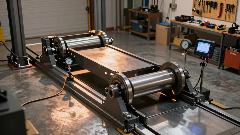
The foundation of precision engineering rests on one critical capability: the accurate measurement of rotational force.
Professionals across automotive, industrial, and aerospace sectors depend on reliable torque measurement to guarantee equipment performs safely and efficiently.
Three essential approaches define modern torque calibration and measurement:
- Torque wrenches verify and apply specified force levels during assembly, establishing baseline accuracy for critical connections.
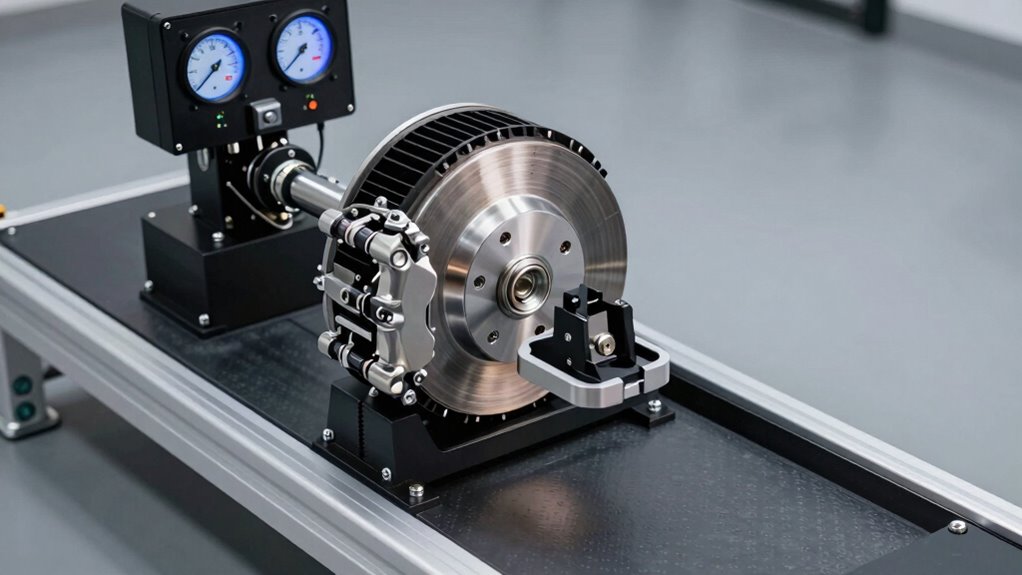
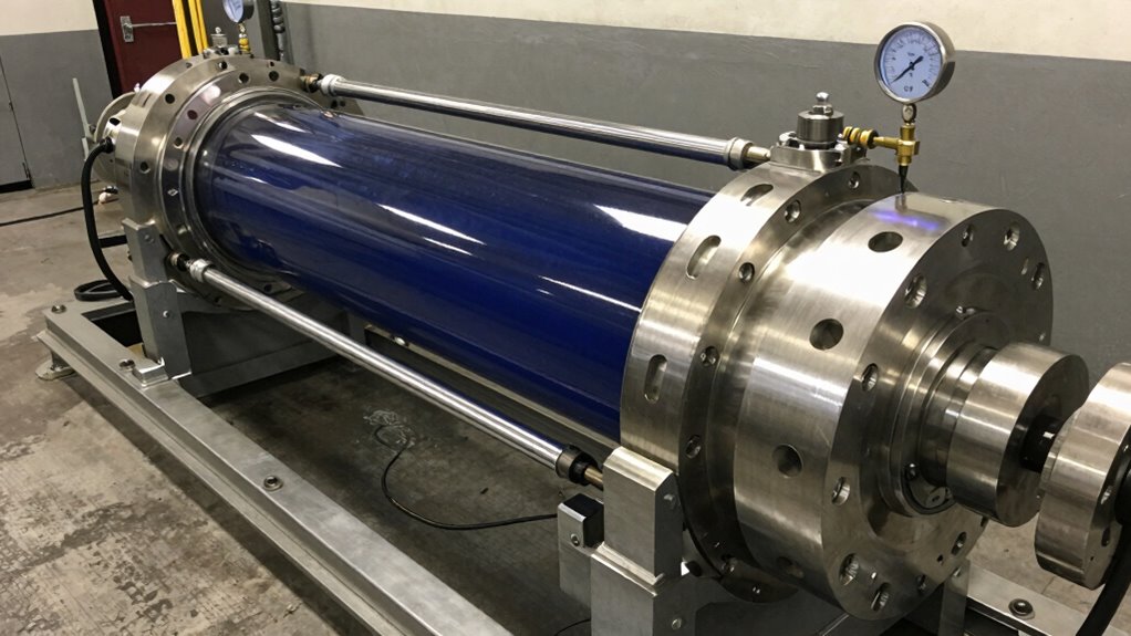
- Rotary sensors measure torque during shaft rotation, employing strain gauges and Wheatstone bridge technology to detect twisting in motors and turbines.
- Contactless sensor types employ magnetic or optical principles, accommodating high-speed applications where traditional methods prove impractical.
Data acquisition systems synchronise torque readings with speed and RPM data, enabling thorough analysis.
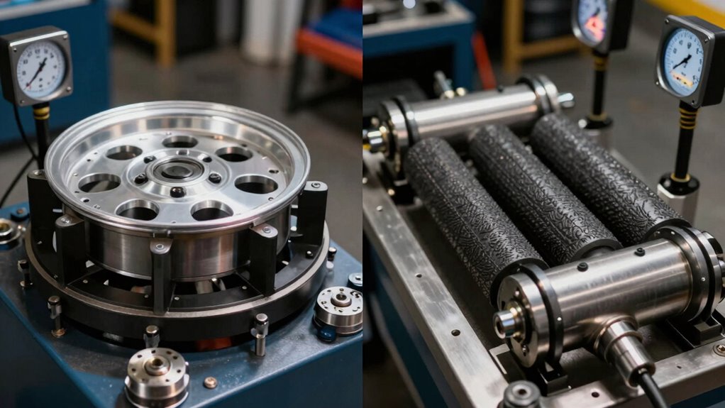
Temperature compensation and dual-range sensors address environmental variables, providing consistent results across diverse testing conditions.
Accessories and parts specifically designed for dynamometers enhance measurement precision and expand testing capabilities beyond standard sensor configurations.
Torque Calculation Errors: What You’re Getting Wrong
While torque measurement tools and sensors provide the foundation for precision work, comprehending how to use them correctly separates reliable results from costly failures.
Common calculation errors stem from neglecting calibration intervals, which allow tools to drift out of accuracy ranges through regular use and environmental wear. Incorrect torque settings—whether too high or too low—compromise component integrity and safety.
Unit inconsistencies create significant problems; using kilograms instead of Newtons produces substantial discrepancies. Environmental factors like local gravity variations and air buoyancy introduce errors exceeding 0.1% without proper correction formulas.
Personnel must reset tools between measurements and verify results with secondary instruments.
Double-checking processes against manufacturer specifications guarantees traceability and prevents assembly failures. Maintaining detailed calibration records prevents overlooked intervals, safeguarding both equipment investment and operational reliability. Regular software updates further enhance measurement accuracy by incorporating the latest calibration algorithms and performance refinements into your testing systems.
How Torque and Power Work Together
Distinguishing between torque and power proves crucial for anyone working with engines, motors, or dynamometer systems, as these two measurements reveal different but complementary aspects of mechanical performance.
Torque represents rotational force, measured in Newton-metres, while power indicates the rate at which work occurs, measured in watts. The relationship between them follows the fundamental equation: P = τω, where angular velocity determines how torque translates into power transmission.
Consider these key distinctions:
- Torque measurement reveals work capacity independent of speed
- Power output depends on both torque and RPM
- Peak power occurs when torque and speed align effectively
Engineers recognise that high torque alone proves insufficient without comprehension of power delivery across the RPM range.
Professional installation and setup services ensure that dynamometer systems capture both parameters simultaneously with precision calibration, enabling professionals to enhance performance characteristics and guarantee systems operate at peak efficiency throughout their operational envelope.
Maximising Torque Efficiency in Motors and Engines
Optimising torque efficiency requires a complex approach that addresses how motors and engines convert energy into useful work.
Motor efficiency strategies encompass multiple interconnected techniques, including field-oriented control for precise power delivery and variable frequency drives that reduce energy consumption by up to 30% during low-demand periods.
Torque optimisation techniques focus on material selection and design enhancement.
Advanced materials like Hiperco alloys increase magnetic flux density to 2.4T, enabling 25% torque increases while reducing motor size by 30%. Low-loss silicon steel laminations and soft magnetic alloys further decrease core losses by up to 3%.
Cooling solutions and lubrication improvements minimise friction and windage losses, maintaining peak efficiency.
Gearbox integration adjusts output torque to match load requirements precisely, preventing unnecessary stress on drivetrain components while extending equipment lifetime.
Custom dynamometer systems with tailored software solutions enable precise measurement and validation of torque optimisation improvements across diverse vehicle configurations and testing scenarios.