
Buying Guides
Dyno Finance South Africa: Easy Funding for Workshops
South African workshop owners reject traditional banks. Dyno Finance proves faster funding exists—here’s what changes everything.
Integrating additional sensors with inertia dynamometers refines engine performance data accuracy, measuring a broader range of parameters and operating conditions. Temperature and pressure sensors account for environmental and operating conditions, while strain gauges and load cells provide direct measurements of torque and force.
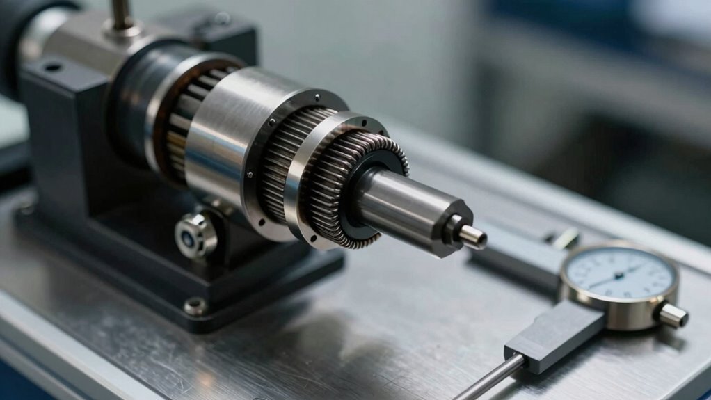
A thorough inertia dynamometer system comprises five crucial components: mechanical unit, control system, sensors, data acquisition system, and user interface.
Strategically integrating sensors, engineers gain a deeper insight into engine dynamics, leading to improved engine design, development, and performance. As the scope of testing expands, the importance of efficient sensor integration and data analysis becomes clear, and the potential for optimisation and further development awaits.
Through strategic integration of additional sensors with inertia dynamometers, engineers can substantially refine the accuracy and thoroughness of engine performance data.
Incorporating sensors such as temperature and pressure sensors enables engineers to account for environmental and operating conditions that affect engine performance, providing a more extensive appreciation of engine behaviour.
Strain gauges and load cells further strengthen data accuracy by providing direct measurements of torque and force, validating and refining inertia-based calculations.
This integration enables engineers to capture a more detailed and accurate representation of engine performance, allowing for more effective optimisation and tuning.
Engineers can gain a deeper insight into engine dynamics, ultimately leading to improved engine design, development, and performance, through leveraging these advanced sensing capabilities.
A thorough inertia dynamometer system comprises five vital components: mechanical unit, control system, sensors, data acquisition system, and user interface.
The mechanical unit, including clutch, gearbox, and inertia mass, enables the measurement of torque and power output.
Sensors, such as load cells, thermocouples, RPM sensors, and analog inputs, provide data on engine performance and operating conditions.
The control system manages the operation of the dynamometer, ensuring seamless interaction between the components and accurate data collection.
It facilitates clutch engagement and disengagement, gearbox shifting, and data acquisition.
The data acquisition system collects and processes data from the sensors, providing real-time information on engine performance and enabling advanced testing and analysis.
This system is critical in facilitating the integration of additional sensors, allowing for more extensive engine testing and analysis.
Understanding these components and their roles enables users to optimise their inertia dynamometer system for improved performance and data accuracy.
When integrating sensors with inertia dynamometers, selecting compatible sensor types and options is vital for accurate measurement and data acquisition.
Sensor integration options, such as direct connection or signal conditioning, must be considered to guarantee seamless data transfer.
Thermocouple sensor compatibility and analog input expansion capabilities are also fundamental factors to evaluate when choosing the right sensors for inertia dynamometer applications.
Efficient sensor integration is crucial for extracting accurate and reliable data from inertia dynamometers.
Selecting the right integration option that aligns with the specific requirements of the application is vital. Several sensor integration options are available, each with its unique advantages and limitations.
A dedicated acquisition system provides a centralized platform for sensor data collection and processing, enabling real-time monitoring and analysis of sensor outputs.
This setup allows for precise control and optimization of the dynamometer's operation.
Integrating sensors directly into the dynamometer's control system streamlines data acquisition and reduces the need for additional hardware.
Some sensors can be connected to external data loggers or computers, providing flexibility and versatility in data collection and analysis.
Careful evaluation of the sensor integration options guarantees seamless data acquisition and optimizes the performance of inertia dynamometers.
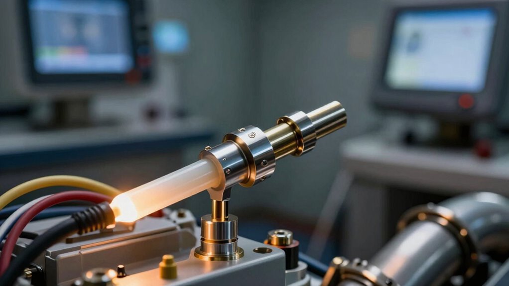
In conjunction with its advanced data acquisition capabilities, the DynEDGE system is designed to seamlessly integrate with a wide range of thermocouple sensors, guaranteeing precise temperature measurement in dynamometer applications.
The system is compatible with multiple thermocouple sensor types, including J, K, T, E, N, and R, allowing for precise temperature measurement in dynamometer applications. Up to 16 thermocouple inputs can be connected directly to the DynEDGE system, eliminating the need for external signal conditioning or amplification units, thus enabling users to monitor temperatures at multiple points in the engine, transmission, or other components.
The system's advanced software provides real-time temperature data acquisition, monitoring, and analysis, enabling users to correlate temperature with engine performance and other parameters.
Additionally, DynEDGE offers optional thermocouple sensor calibration and verification services to certify accurate temperature measurements and compliance with industry standards.
Users can confidently rely on precise temperature measurements to optimise engine performance, improve efficiency, and reduce emissions.
Beyond thermocouple sensors, the DynEDGE system's analog input expansion capabilities enable users to integrate a broader range of sensors, substantially expanding the scope of their testing and data analysis.
This feature allows users to connect additional sensors, providing a more in-depth appreciation of their testing environment.
The DynEDGE system is compatible with a range of sensor types, including strain gauges, accelerometers, and potentiometers, which measure different physical parameters such as force, acceleration, and position.
Pressure sensors and flow meters provide insights into pressure and flow rates.
Up to 16 analog input channels are available, allowing users to connect multiple sensors and expand their testing capabilities.
Users can select from a range of sensor connection options, including screw-terminal blocks, D-subminiature connectors, and M12 connectors, to guarantee compatibility with their existing sensor infrastructure.
The DynEDGE software provides real-time data acquisition and monitoring capabilities, allowing users to visualize and analyze data from their additional sensors and integrate it with their dynamometer testing data.
Inertia dynamometers can accommodate additional sensors through diverse connection options, including analog input channels, digital communication interfaces, and wireless protocols.
Analog input integration enables the measurement of parameters such as temperature and pressure, while digital signal processing enables the acquisition of data from sensors using protocols like CAN bus or MODBUS.
The choice of integration method depends on the type of sensor and the specific requirements of the testing application.
Several integration methods are available for connecting additional sensors to an inertia dynamometer, each offering distinct advantages and limitations.
These methods enable the incorporation of supplementary sensor data into the control system, enhancing the comprehensive testing and measurement capabilities of the dynamometer.
Digital communication protocols, such as Ethernet, CAN, or USB, connect sensors directly to the dynamometer's control system, facilitating high-speed data transfer and minimizing wiring complexity.
Analog signal conditioning converts sensor signals to a compatible format for the dynamometer's control system, ensuring accurate data acquisition and processing.
Sensor hubs and gateways centralize sensor connections and data processing, simplifying system integration and reducing the number of connections to the dynamometer.
Modular sensor interfaces implement modular designs that enable easy swapping or addition of sensors, streamlining system configuration and reconfiguration.
Custom integrations develop tailored solutions for unique sensor requirements, ensuring seamless integration with the dynamometer's control system.
Analog input integration is a fundamental method for incorporating supplementary sensors into an inertia dynamometer's control system.
The YourDyno Ultimate instrumentation kit, for instance, features eight analogue inputs for integrating a wide range of sensors, including thermocouples, pressure sensors, and flow meters. These analogue input channels have a 16-bit resolution and can be configured to measure voltage, current, or resistance, providing users with flexibility and precision.
To integrate a sensor using analogue input integration, users simply connect the sensor to the analogue input channel and configure the channel settings through the PC software.
The software allows users to assign a specific engineering unit to each analogue input channel, enabling the display of measured values in the desired unit. Furthermore, the software provides a calibration feature for analogue input channels, enabling users to adjust the measured values to match the sensor's specifications.
This guarantees accurate and reliable data collection, which is vital for precise control and monitoring of the dynamometer. Users can seamlessly integrate additional sensors into their inertia dynamometer's control system, expanding its capabilities and improving its aggregate performance.
Tapping into the power of digital signal processing (DSP) enables users to access a wealth of possibilities for integrating additional sensors into their inertia dynamometer's control system.
DSP techniques such as filtering, amplification, and analogue-to-digital conversion enable the integration of sensors like temperature, pressure, and vibration sensors.
Some key aspects of digital signal processing in inertia dynamometer applications include applying DSP algorithms like Fast Fourier Transform (FFT) and wavelet analysis to extract meaningful information from sensor data and improve measurement precision.
Selecting appropriate communication protocols for sensor integration, such as analogue-to-digital converters, UART, SPI, CAN, and Ethernet, is also crucial.
Optimising the sampling rate and resolution of the analogue-to-digital converter (ADC) guarantees accurate and reliable sensor data integration.
Compensating for sensor errors and non-idealities, such as offset, gain, and non-linearity, improves total measurement accuracy and reliability.
Enhancing the system's general performance and functionality of the inertia dynamometer system through advanced DSP techniques further optimises the system.
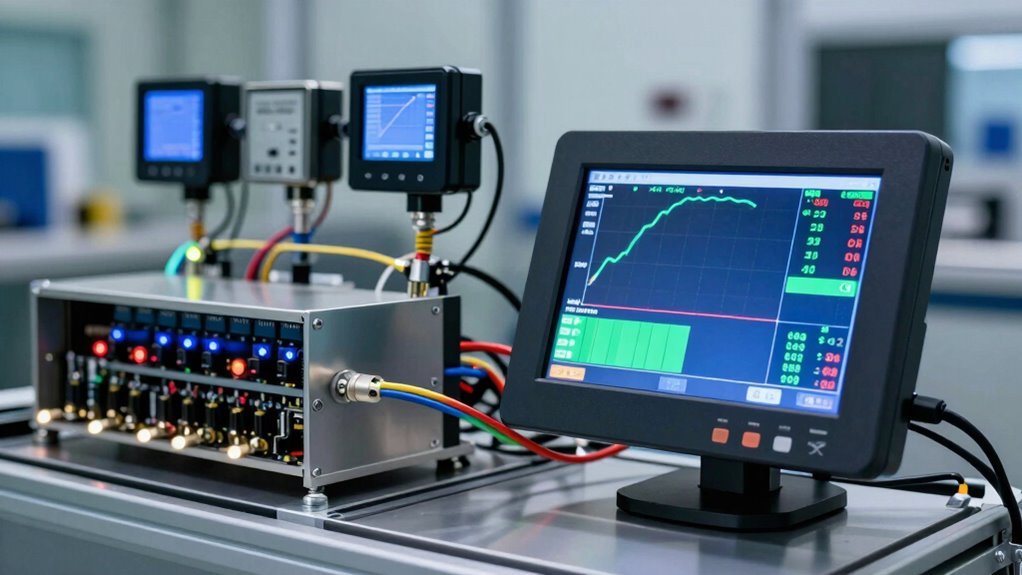
In the realm of Inertia Dynamometers, data acquisition and analysis software assumes a vital role in uncovering the intricacies of engine performance.
This software facilitates the integration of additional sensors, including temperature, pressure, and vibration sensors, to provide an in-depth comprehension of engine behaviour.
The software's data acquisition capabilities enable high-speed data collection, with sampling rates of up to 1000 Hz, capturing detailed information about engine performance during testing.
Sophisticated data analysis tools, such as frequency analysis and statistical process control, can be applied to the collected data to identify trends, patterns, and anomalies in engine performance.
The software can be configured to trigger data collection based on specific events, such as engine start-up or shift points, ensuring critical data capture during testing.
Data can be exported in multiple formats, including CSV, Excel, and MATLAB, to enable further analysis and modelling using external tools and software.
This enables engineers to gain valuable insights into engine performance, allowing optimisation of engine design and operation.
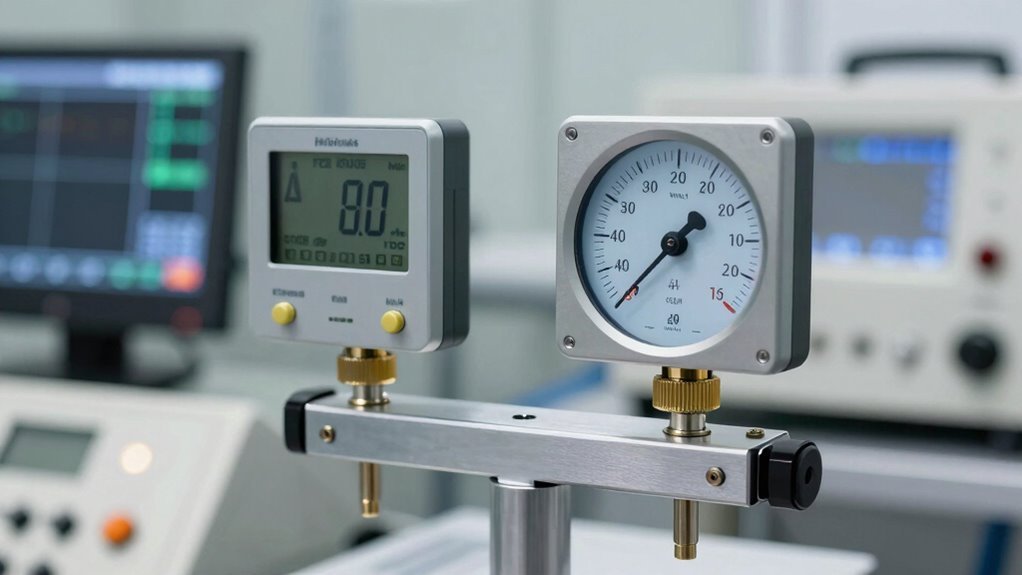
Sensor calibration and validation procedures are crucial steps in guaranteeing the integrity of the data acquisition process, as the accuracy of sensor data is paramount to reliable engine performance testing.
These procedures certify that the sensor data is reliable, consistent, and accurate, which is critical for making informed decisions about engine performance.
Sensor calibration involves comparing the sensor's output to a known reference signal to certify accuracy within ±0.1% of full scale.
This process typically involves a two-point or multi-point calibration method, where the sensor's output is recorded at multiple points across its operating range and compared to the reference signal.
Sensor calibration for inertia dynamometers guarantees accuracy within ±0.1% of full scale.
Validation procedures involve verifying the sensor's performance under differing operating conditions.
The calibration process typically involves a two-point or multi-point calibration method.
Validation tests may include linearity, hysteresis, and repeatability tests.
Regular recalibration and revalidation are recommended to maintain sensor accuracy.
The fusion of data from multiple sensors with Inertia Dynamometer data yields significant benefits, including improved data quality and sensor harmony effects.
By combining data from diverse sensors, engineers can eliminate individual sensor limitations, reduce measurement uncertainty, and gain a more thorough grasp of engine performance.
This multi-sensor approach enables the detection of subtle patterns and relationships that may not be apparent from single-sensor data, ultimately leading to more accurate and reliable test results.
One of the most significant advantages of integrating sensors with inertia dynamometers is the improvement of data quality through multi-sensor data fusion.
Combining data from diverse sensors provides users with a more in-depth grasp of engine performance, leading to refined data quality.
The benefits of multi-sensor data fusion for data quality refinement are numerous.
It increases the accuracy and reliability of engine performance measurements. This approach enables the identification of patterns and correlations that may not be apparent from individual sensor data.
Furthermore, it reduces the impact of individual sensor errors or noise, resulting in more sturdy and reliable engine performance measurements.
Multi-sensor data fusion also allows for the measurement of additional parameters, such as engine knock or vibration, providing further insights into engine performance and behaviour.
This approach provides a more nuanced comprehension of engine behaviour and performance, enabling more precise optimisation and tuning.
The fusion of multiple sensor data with inertia dynamometer data reveals hidden patterns and relationships that would remain obscure when relying on individual sensors.
Sensor integration effects enable the detection of subtle patterns and relationships that may not be apparent from individual sensor data. Combining data from multiple sensors, such as accelerometers, thermocouples, and pressure sensors, with inertia dynamometer data provides a more in-depth knowledge of engine performance and behaviour.
This data fusion improves the accuracy of torque calculation and engine performance measurement, with enhancements of up to 5 per cent compared to using a single sensor. Furthermore, sensor integration effects provide insights into engine dynamics, including combustion efficiency, knock detection, and frictional losses, which can be utilised to optimise engine design and performance.
Real-time monitoring and control of engine parameters become possible, enabling quicker response to changes in operating conditions and improved total engine efficiency.
Racing engines, like finely tuned athletes, require precise calibration to tap their full potential.
Integrating additional sensors with inertia dynamometers has proven to be a game-changer in optimising engine performance. Several case studies have demonstrated the significant improvements that can be achieved through this harmony.
A Formula 1 team saw a 1.2% increase in engine power output after optimising engine calibration using data from the dynamometer.
In a study with a NASCAR team, inertia dyno data helped improve engine performance, resulting in a 3.5 horsepower increase, which led to a 0.2-second reduction in lap time.
A motorcycle manufacturer used inertia dyno to optimise engine performance, resulting in a 5.1% increase in horsepower and a 3.2% increase in torque.
A study on a high-performance sports car found that inertia dyno data helped optimise engine calibration, resulting in a 2.1% increase in horsepower and a 1.9% increase in torque.
A case study with a diesel engine manufacturer used inertia dyno to optimise fuel injection timing, resulting in a 4.5% increase in torque and a 2.2% increase in fuel efficiency.
These studies demonstrate the potential of integrating additional sensors with inertia dynamometers to release advanced engine performance.
Engine manufacturers and racing teams can gain a competitive edge, achieving improved power output, torque, and fuel efficiency, through the precision and accuracy of these sensors.
Optimizing Engine Design With Sensor Data
Engine architecture is a delicate balancing act, where even slight modifications can have far-reaching consequences on performance.
Integrating additional sensors with inertia dynamometers provides engine designers with a wealth of data to inform design decisions and optimise engine performance. This data-driven approach enables the identification of areas for improvement, allowing designers to refine engine architecture and tap into hidden potential.
Sensor data provides valuable insights into engine behaviour, enabling fine-tuning of critical components such as fuel injection systems, ignition timing, and cylinder head design.
Analysing data on parameters such as torque, speed, and vibration enables designers to optimise engine performance, reducing emissions and improving fuel efficiency. Advanced analytics and modelling techniques also enable the simulation of multiple design scenarios, reducing the need for physical prototypes and accelerating the development process.
As a result, engine designers can create more efficient, powerful, and environmentally friendly engines that meet the demands of an increasingly complex and competitive market.
As the demand for more efficient and environmentally friendly engines continues to drive innovation, researchers are pushing the boundaries of sensor technology to reveal new insights from inertia dynamometers.
The future of inertia dynamometer sensors holds much promise, with several exciting developments on the horizon.
Researchers are investigating the integration of advanced sensors, such as piezoelectric and fibre optic sensors, to refine the accuracy and precision of inertia dynamometer measurements.
The development of advanced materials and nanotechnology is expected to lead to the creation of smaller, more sensitive, and higher-resolution sensors for inertia dynamometers.
Future inertia dynamometer sensors may incorporate artificial intelligence and machine learning algorithms to improve data analysis and provide real-time insights into engine performance.
The use of wireless sensor networks and IoT technologies is being investigated to enable real-time monitoring and data transmission from inertia dynamometers, reducing the need for physical connections and improving testing efficiency.
Next-generation inertia dynamometer sensors may include advanced thermocouple and accelerometer designs that can withstand high temperatures and vibrations, enabling more accurate measurements in extreme testing conditions.
These advancements in sensor technology will enable engineers to gather more accurate and detailed data, leading to better engine design and optimisation.
Integrating Additional Sensors with Inertia Dynamometers
Enhancing Data Accuracy with Sensors
At Hyper Power, we understand that inertia dynamometers, while widely used to measure engine performance, can be limited in their ability to provide an exhaustive grasp of engine behaviour. Integrating additional sensors can substantially augment the accuracy of data collected and provide a more detailed insight into engine performance.
Inertia Dynamometer System Components
A typical inertia dynamometer system consists of a dynamometer, a load unit, and a control system. The dynamometer measures the torque and speed of the engine, while the load unit simulates diverse load conditions. The control system manages the test procedure and collects data from the dynamometer and load unit.
Compatible Sensor Types and Options
Several types of sensors can be integrated with inertia dynamometers, including temperature sensors, pressure sensors, flow sensors, and vibration sensors. These sensors can provide valuable information on engine parameters such as combustion pressure, exhaust gas temperature, and oil pressure.
Integration Methods for Additional Sensors
Sensors can be integrated with inertia dynamometers using diverse methods, including analogue-to-digital conversion, digital signal processing, and data acquisition software. The choice of integration method depends on the type of sensor and the required data acquisition rate. If you have any questions about integrating additional sensors with inertia dynamometers, contact us at Hyper Power to discuss our Custom Dyno Solutions.
Data Acquisition and Analysis Software
Data acquisition and analysis software play a vital role in integrating additional sensors with inertia dynamometers. Software such as LabVIEW, MATLAB, and Python can be used to collect, analyse, and visualise data from multiple sensors. Our team at Hyper Power can provide Training and Certification on data acquisition and analysis software to ensure you get the most out of your system.
Benefits of Multi-Sensor Data Fusion
The integration of multiple sensors with inertia dynamometers enables the fusion of data from different sources, providing a more thorough insight into engine behaviour. This can lead to improved engine design, optimisation, and testing. Our Diagnostics and Performance Analysis services can help you unlock the full potential of your engine.
Case Studies of Enhanced Engine Performance
Several case studies have demonstrated the benefits of integrating additional sensors with inertia dynamometers. For example, the use of temperature sensors to monitor engine coolant temperature has been shown to improve engine efficiency and reduce emissions. Hyper Power can assist with Installation and Setup of your inertia dynamometer system to ensure optimal performance.
Optimising Engine Design with Sensor Data
The data collected from multiple sensors can be used to optimise engine design and performance. For example, data on combustion pressure and temperature can be used to optimise engine compression ratio and fuel injection timing. Our team at Hyper Power can provide Technical Support and Maintenance to ensure your system is always running at its best.
Future Developments in Inertia Dynamometer Sensors
The development of new sensor technologies, such as wireless sensors and nanosensors, is expected to further augment the capabilities of inertia dynamometers. These advances will enable the collection of more accurate and detailed data, leading to further improvements in engine design and performance. Hyper Power offers Software Updates and Upgrades to ensure you stay ahead of the curve.
Conclusion
The integration of additional sensors with inertia dynamometers enhances data accuracy and provides a more thorough insight into engine behaviour. This leads to improved engine design, optimisation, and testing, and is expected to further advance with the development of new sensor technologies. If you have any questions about integrating additional sensors with inertia dynamometers, contact us at Hyper Power to discuss our Rental Services, Dynamometer Testing Services, and Accessories and Parts.
South African workshop owners reject traditional banks. Dyno Finance proves faster funding exists—here’s what changes everything.
Most technicians miss critical factors that cause speed sensor failures. Learn what separates reliable diagnostics from cascading system problems.
Narrowband sensors are costing you power. Learn why wideband O2 technology separates real tuning from guesswork—and how to implement it correctly.
Your dyno numbers are incorrect. Temperature, humidity, and pressure quietly distort every measurement—correction factors reveal what your engine actually produces.

Heavy-duty fleets waste thousands on brake wear. One controller feature changes everything—here’s why most managers miss it.
Modern dyno testing exposes a hidden gap between leading DAQ platforms and the rest. What are you missing?

Hyperwin4 rewrites dyno tuning with AI diagnostics and real-time cloud power. But are your devices ready for this shift?
Master roller-to-hub conversion or watch your drivetrain fail. Learn the precision steps that separate reliability from costly mistakes.