Meta Description:
Your transmission’s synchroniser hub is silently working to keep your AWD running—but most drivers have no idea what it does. Friction-based mechanisms, blocking rings, and spline engagement sound complex, yet they’re the difference between smooth power delivery and catastrophic drivetrain failure. Miss the early warning signs, and you’re looking at repairs that could drain your wallet. Learn what actually happens inside your transmission before it’s too late.
Hub Synchronisation: Why It Matters
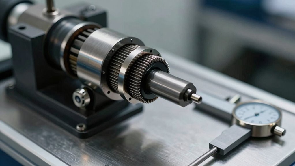
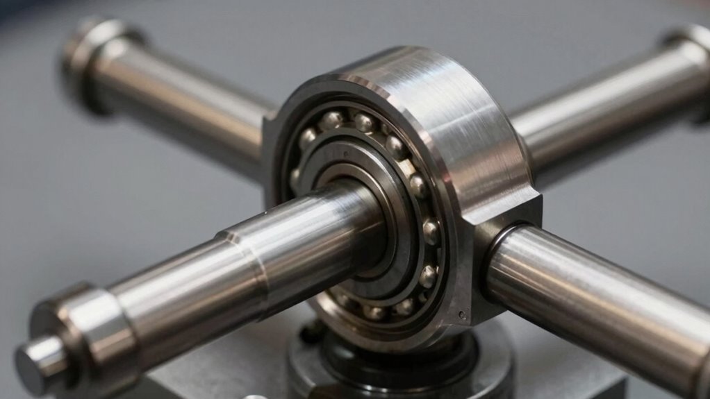
At the heart of every transmission lies a component called the synchroniser hub, a precisely machined part that serves as the mechanical foundation for matching rotational speeds during gear shifts.
The hub, splined directly to the transmission output shaft with a tight interference fit, rotates at the exact speed of the shaft without any slippage.
In AWD systems, hub performance proves critical for preventing drivetrain binding caused by mismatched wheel speeds.
The hub enables friction-based synchronisation between components, ensuring consistent rotational speed matching during engagement. This precise torque distribution across axles prevents stress on drivetrain components and maintains smooth power delivery. Synchronisers operate as friction clutches to facilitate smooth gear engagement without violent clashes between components.
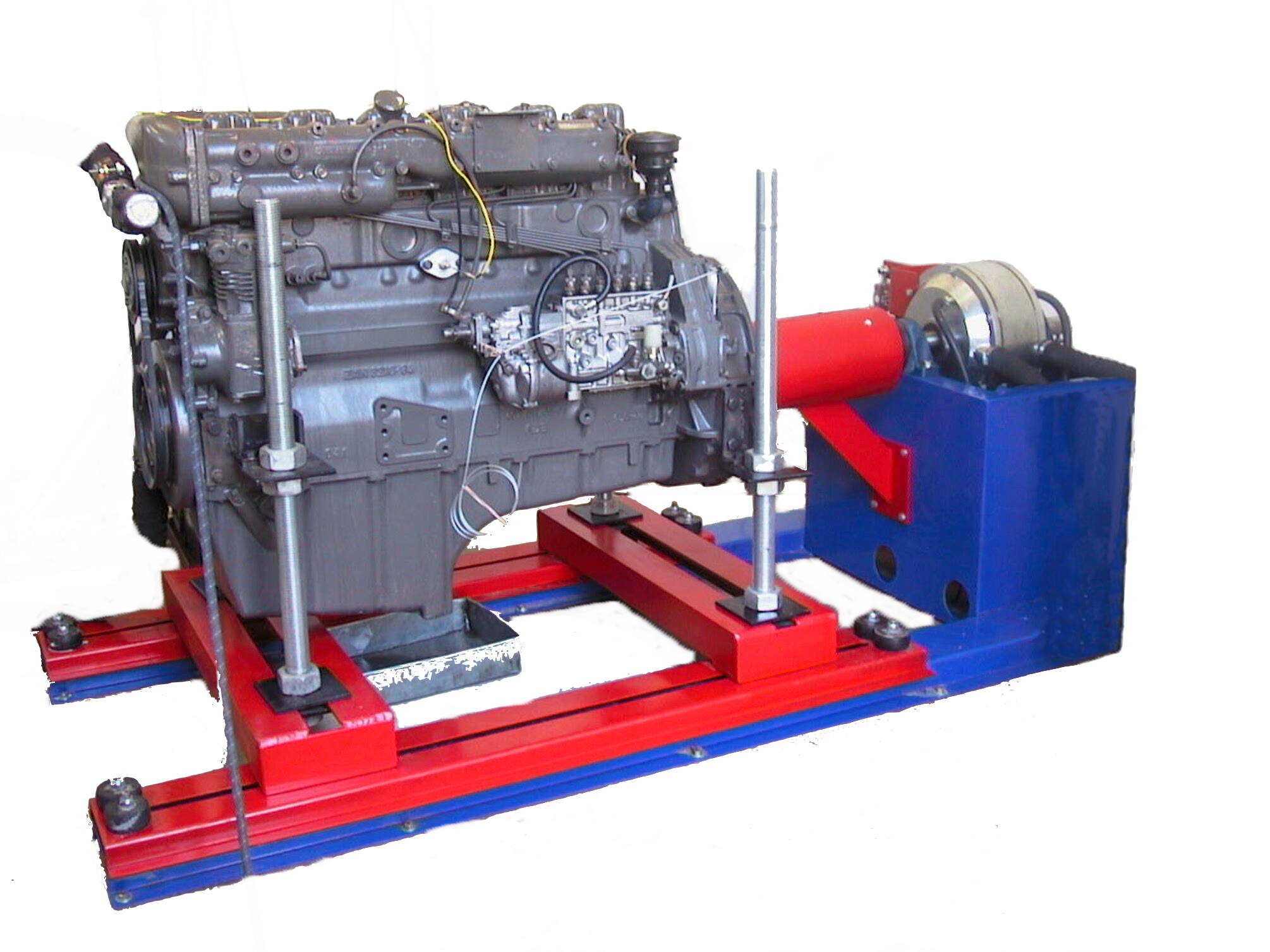
On chassis dynamometers specifically, proper hub synchronisation allows safe low-speed operation before ramping up full load testing. Advanced dynamometer technology provides comprehensive data collection across varying load conditions to validate hub synchronisation performance.
This foundational component fundamentally guarantees reliable vehicle performance data during complex testing protocols.
How Blocking Rings Synchronise Gear Speed?
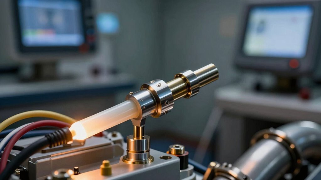
Within the transmission assembly, blocking rings function as precision friction devices that eliminate speed mismatches between the input shaft and the gear being engaged. These cone-shaped components generate friction torque interactions through direct contact with the gear cone surface, equalising rotational speeds during the shift sequence.
The blocking ring functionality operates through a mechanical sequence. When shift sleeves apply pressure, struts push the ring against the gear cone, initiating friction contact. The blocker ring is made from special brass alloy to withstand repeated friction cycles during transmission operation.
This friction torque, derived from the coefficient of friction and cone radius, gradually matches the gear speed to the shaft speed, reducing speed differential to approximately 50-100 RPM.
Once speeds synchronise, the ring’s external teeth align with sleeve grooves, permitting gear engagement. This controlled synchronisation prevents grinding and guarantees smooth, efficient power transfer during AWD hub operation.
Synchroniser Keys: The Hub’s Control Mechanism
Synchroniser keys, also known as struts, dogs, or pressure pieces, represent the critical control elements that orchestrate smooth gear shifts in AWD hub assemblies.
These components sit within machined slots on the synchroniser hub, positioned to rotate with the hub while moving axially relative to the sliding sleeve.
Spring tension maintains consistent pressure on the keys, keeping them properly positioned against the blocker ring. This spring interaction guarantees reliable friction contact during the synchronisation process. The locking elements within the synchroniser assembly work in coordination with the keys to maintain the sliding sleeve’s position and assist in synchronisation.
As the sleeve moves toward the gear, the keys engage slots in the synchroniser ring, applying necessary load for speed matching. Our cutting-edge software solutions enhance the precision and reliability of modern AWD hub testing systems.
Key alignment proves essential for peak performance. When speeds equalise, the keys and notches align perfectly, allowing the blocker ring to lock with the synchroniser.
This precise coordination enables seamless gear changes in high-performance AWD systems.
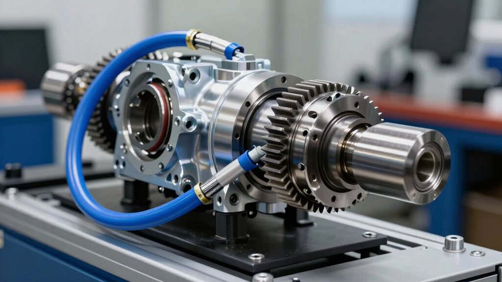
How Hub Synchronisation Works During a Shift
Comprehending the mechanics of synchroniser hub function requires examining the precise sequence of events that unfolds when a driver selects a new gear. The synchroniser hub connects rigidly to the output shaft via splines, enabling controlled axial movement while maintaining rotational alignment. During gear engagement, the sliding sleeve advances, positioning locking elements that apply load to the synchroniser ring. The blocker ring’s conical surface fits onto the speed gear cone to facilitate this synchronisation process.
| Phase |
Component Action |
Friction Characteristics |
| Initial Contact |
Synchroniser ring meets gear cone |
Friction torque generates |
| Speed Matching |
Shaft and gear speeds align |
Angular difference reduces to zero |
| Completion |
Friction force diminishes |
Teeth fully mesh |
The friction characteristics between the synchroniser ring and machined cone reduce angular speed differences, achieving seamless gear engagement without grinding or shock loads that compromise drivetrain integrity.
Diagnose Hub Synchronisation Failures
When hub synchronisation fails, the entire drivetrain experiences cascading problems that range from grinding noises to complete loss of traction control.
Technicians should first inspect the vacuum system, as low vacuum to hubs indicates solenoid issues or deteriorated hoses that prevent proper engagement. A hand vacuum pump on the check valve confirms system integrity.
Next, examine clutch adjustment specifications carefully, since improper alignment voids transmission warranties and accelerates component wear. Clutch drag can rapidly destroy synchronisers if left unaddressed, making regular monitoring essential for transmission longevity.
Missing or damaged dowel pins frequently cause misalignment, leading to dragging that destroys synchronisers within several shifts.
Electronic diagnostics reveal additional failures through scanner PIDs monitoring 4WD solenoid status and sensor responses.
Battery disconnects lasting five to ten minutes reset electronic control modules when flashing warning lights persist.
These systematic checks isolate whether mechanical, vacuum, or electronic components require replacement.
Improve Shift Speed and Smoothness
Once hub synchronisation operates reliably, attention shifts to enhancing the speed and quality of gear changes themselves.
Shift efficiency depends primarily on friction management within the cone interfaces, where improved surface contact accelerates speed equalisation between components. Spring-loaded struts maintain consistent blocking ring pressure throughout the engagement process, reducing the RPM delta more rapidly and smoothly.
Advanced cone geometries and precise press-fitting techniques minimise friction variability, enabling predictable shift timing. As friction torque decreases upon synchronisation, the sleeve advances faster into full engagement.
Chamfered tooth profiles on blocker rings guide this final meshing phase seamlessly, preventing binding and hesitation.
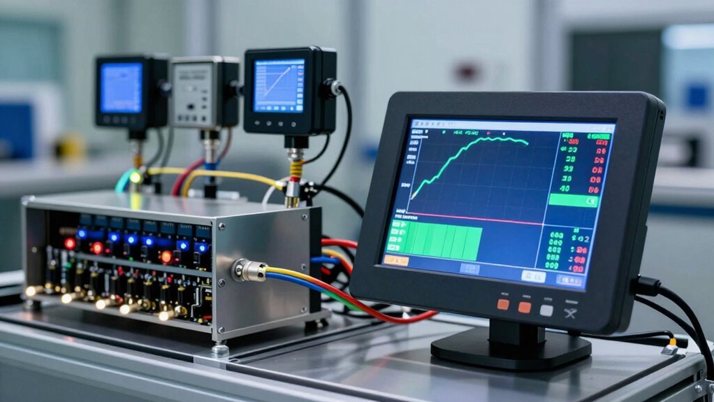
Professional tuning shops utilise dynamometer data to validate shift characteristics under load, identifying friction anomalies before they compromise performance. High-performance testing systems from leading dynamometer providers ensure precision measurement of synchronisation behaviour across diverse vehicle platforms.
This measured approach changes gear changes from mechanical necessity into enhanced mechanical expression, providing the responsiveness discerning drivers expect.
Worn Splines and Stripped Teeth: When Replacement Is Needed
Spline wear and tooth stripping represent critical failure points in AWD hub assemblies, manifesting through distinctive auditory and tactile symptoms that demand immediate attention.
Identifying early warning signs—such as noise during turns, vibration through the steering wheel, and clunking sounds during acceleration—allows technicians to assess whether repair or full replacement is necessary.
Comprehension of the progression from minor wear to catastrophic failure guarantees that owners can intervene before secondary damage cascades through the entire drivetrain system.
Spline Wear Identification Signs
How can operators recognise the early warning signs of spline degradation before catastrophic drivetrain failure occurs?
Visual inspection reveals the most telling indicators of spline wear. Completely stripped splines become visible on the transfer case coupler or transmission output shaft, displaying rounded or missing teeth compared to sharp edges on new components.
Noticeable wear patterns emerge when lubrication fails in dry-running systems, accelerating deterioration.
Audible symptoms often precede visible damage. Grinding, whining, or clicking noises during acceleration signal worn splines requiring immediate attention.
Combined with dashboard warning lights for AWD or traction control, these audible cues warrant professional spline inspection techniques.
Effective spline wear prevention demands regular maintenance checks and proper lubrication protocols.
High-mileage vehicles or those subjected to off-road use face accelerated degradation.
Early identification through systematic inspection prevents complete spline failure and costly transmission replacements.
Stripped Tooth Damage Assessment
When audible grinding and visual spline wear progress beyond the early warning stage, operators face a critical decision point: assess whether components can be restored or require full replacement. Stripped teeth manifest as missing or sheared sections on gear surfaces, typically from impact or excessive loading during high-power dyno sessions.
Critical inspection indicators include:
- Sharp edges or flattened profiles on spline teeth, accompanied by metal shavings around the hub
- Gear tooth loss exceeding 20% of surface area, mandating immediate replacement
- Endplay surpassing 0.020 inches from spline wear, compromising wheel speed sensors
Stripped tooth consequences cascade through the powertrain, affecting differential gears and drive shafts.
Tooth loss prevention requires proper synchronisation during AWD testing, particularly above 1000 whp. Hyper Power’s proactive system monitoring services can help detect early signs of wear before catastrophic failure occurs.
Professional assessment determines replacement necessity, protecting long-term equipment integrity.
Replacement Timing And Urgency
Once grinding noises emerge from the wheel corners and visual inspection confirms spline wear approaching 50% of the tooth profile, operators enter a critical window where replacement decisions become unavoidable.
The replacement indicators signal progression toward differential or gear damage, making immediate action essential for cost-effective maintenance schedules.
Hub serrations worn smaller than OEM diameter specifications demand component replacement to prevent axle back-out or spline exposure beyond safe limits.
Delaying action risks escalation to expensive drivetrain repairs, particularly in frequent wear vehicles like Range Rover Sport and LR3 models from 2005-2009.
Applying temporary fixes such as epoxy should be avoided, as welding or separation may become necessary later.
Professionals within the community recognise that proper replacement timing protects both equipment integrity and operational safety, fundamentally preserving long-term performance and reliability. Professional installation and expert calibration techniques ensure that replacement components are configured correctly to maintain precise synchronisation and prevent premature wear recurrence.
Transmission Synchronisers vs. Unsynchronised Gearboxes
The fundamental difference between synchronised and unsynchronised transmissions lies in how they manage gear engagement during shifts. Synchronised gears employ cone clutches that automatically match shaft speeds before engagement, enabling smooth shifts.
Unsynchronised transmission types, conversely, require drivers to manually match speeds through double-clutching or float shifting techniques.
Key distinctions between transmission types:
- Synchronised systems feature cone-and-collar mechanisms equalising shaft speeds, dominating modern passenger vehicles.
- Unsynchronised designs use sliding square cogs, preferred in semi-trucks and heavy machinery for superior durability.
- Race transmissions often employ dog-type configurations without synchros, enabling faster shifts than synchronised alternatives.
Modern synchronised gears represent the standard for everyday driving, offering reliability and ease of operation.
Commercial applications, however, frequently prefer unsynchronised systems due to their sturdy construction and performance advantages under demanding conditions.