Wideband O2 Sensors: Why Your Tuning Setup is Probably Wrong
Most tuners are flying blind with narrowband sensors, chasing performance gains that stay perpetually out of reach. Wideband O2 sensors shatter this limitation by delivering real-time air-fuel ratio data across your entire operating range—but installation and controller integration demand precision that separates dyno queens from street monsters. Lambda versus AFR, naturally aspirated versus forced induction—each demands a different strategy, and getting it wrong costs you power, reliability, and credibility at the track.
Why Wideband Beats Narrowband Technology
Regarding air-fuel ratio measurement, the difference between narrowband and wideband oxygen sensors fundamentally shapes how effectively an engine can be tuned and controlled.
Narrowband sensors operate within severe limitations, outputting only binary signals that indicate whether the fuel mixture is rich or lean relative to 14.7:1 stoichiometry. This restricted feedback forces ECUs to overcorrect continuously, oscillating between extremes without quantitative precision.
Wideband advantages become apparent through continuous linear output across a 10:1 to 18:1 range, providing exact air-fuel ratios on a 1-5V scale.
Professional tuning demands wideband’s superior accuracy. Narrowband fails beyond stoichiometric conditions, proving inadequate for high-performance applications. When access to diagnostic tools or tuning platforms becomes restricted due to security service blocks, alternative offline calibration methods become necessary for maintaining engine performance data.
Wideband maintains precision across all operating conditions, enabling stable closed-loop control and faster ECU adjustments. Furthermore, wideband heaters reach operational temperature in approximately 10 seconds, compared to narrowband’s sluggish 600°F warmup, reducing cold-start fuel control lag considerably.
How Wideband Sensors Measure Air-Fuel Ratio
Comprehending wideband superiority requires examining the actual mechanics behind how these sensors generate their precise measurements. The sensor contains a pumping cell and reference cell separated by a porous diffusion gap, functioning as two oxygen sensors in sandwich configuration.
The pumping cell applies positive or negative current to regulate oxygen into or out of the reference cell, maintaining lambda one conditions for accurate measurement. Current supplied to the pumping cell remains proportional to exhaust oxygen amount, with oxygen ions flowing based on differences between exhaust and outside air. This enhanced sensitivity enables the sensor to provide more accurate quantitative measurements compared to traditional narrowband oxygen sensors.
Through sensor calibration and sophisticated signal processing, this design produces a linear output corresponding to exact air-fuel ratios. Unlike narrowband sensors, wideband technology delivers smooth, predictable voltage changes ranging from extremely rich to lean conditions, enabling precise engine management and improved combustion efficiency.
Operating Temperature and Sensor Warm-Up Requirements
Because wideband oxygen sensors operate at fundamentally higher temperatures than their narrowband counterparts, grasping thermal requirements becomes critical for reliable engine management and emissions control.
Wideband sensors require 700-800°C (1292-1472°F) to function properly, nearly double the 350-400°C needed for narrowband units.
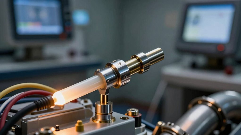
Internal heater circuits enable rapid warm-up, achieving operating temperature in under 20 seconds through duty-cycle control. This heater efficiency guarantees the Nernst cell reaches 750-850°C quickly, providing stable readings within 100 milliseconds once warm. The heater circuit is typically pulse width modulated to control heat based on engine temperature and prevent overheating conditions.
The heater maintains sensor durability by providing consistent thermal conditions before exhaust gases fully warm the element. Early temperature achievement prevents open-loop operation, allowing the engine computer to access accurate air-fuel data immediately.
Excess heat beyond target temperatures triggers automatic sensor shutdown, protecting against damage and maintaining long-term reliability.
Once the wideband sensor reaches its ideal operating temperature and delivers stable readings, the next phase involves proper physical installation to maintain that performance.
Correct sensor placement determines measurement accuracy and longevity, requiring strategic positioning within your exhaust system.
Sensor Placement Fundamentals
Position the sensor six inches after the exhaust collector for naturally aspirated engines, or twenty-four inches downstream from supercharger outlets on forced-induction applications. This distance prevents heat damage while capturing representative air-fuel data. Avoid placing the sensor too close to the turbo outlet, as excessive heat exposure will prematurely degrade the sensor.
Mount the sensor perpendicular to exhaust flow using a weld-in bung, securing it firmly to eliminate vibration.
Wiring Techniques
Connect the red wire to switched ignition power and the black wire to chassis ground using proper gauge sizing.
Route wiring assemblies away from heat sources and moving components, securing connections with zip ties for long-term reliability.
Stoichiometric Targets: The 14.7:1 Baseline and Beyond
The stoichiometric ratio of 14.7:1 serves as the chemical baseline for complete combustion in petrol engines, yet ideal air-fuel mixture varies considerably depending on engine load and operating conditions.
While idle and cruise phases benefit from staying near this stoichiometric target for emissions control, wide-open throttle and heavy acceleration demand richer mixtures, typically ranging from 12:1 to 13:1, to maximise power output safely. Turbochargers increase air density, resulting in denser mixtures that raise peak cylinder pressure and further necessitate richer AFR adjustments to prevent knock. Advanced dynamometer technology enables precise measurement of these AFR variations across different operating scenarios to optimise tuning strategies.
Comprehending when and how to adjust from the 14.7:1 baseline allows engine tuners and technicians to balance performance gains with reliability and emissions compliance across different driving scenarios.
Understanding Stoichiometric Baseline
At the foundation of modern engine management lies a deceptively simple concept: the stoichiometric air-fuel ratio, a chemically ideal proportion where exactly enough air burns all fuel completely with no excess of either remaining.
For petrol engines, this baseline sits at approximately 14.7 parts air to 1 part fuel by mass, representing the stoichiometric importance in achieving peak combustion efficiency.
This precise ratio guarantees complete fuel burn, minimising unburned hydrocarbons and maximising energy extraction from each drop of fuel.
Engines operate effectively within an 8:1 to 18.5:1 range, yet the 14.7:1 point delivers the theoretical best balance between power output and fuel economy.
Wideband oxygen sensors measure actual air-fuel ratios against this stoichiometric baseline, enabling real-time adjustments that maintain highest combustion efficiency across varying driving conditions.
Load-Dependent Target Adjustments
While the stoichiometric 14.7:1 baseline provides a solid foundation for combustion efficiency, real-world engine operation demands far more sophistication than holding a single target across all driving conditions.
Load mapping divides engine operation into distinct zones—low, medium, and high load areas—each requiring specific target calibration for ideal performance and safety.
Low load conditions demand leaner targets for fuel economy, while medium load operation balances efficiency with drivability. High load scenarios require richer targets to protect engine components under pressure or nitrous conditions.
This stratified approach to target calibration guarantees tuners achieve precise control across the entire operating envelope.
Wideband sensors enable continuous monitoring throughout these zones, allowing real-time adjustments that keep engines running safely and efficiently regardless of driving demands. Our dynamometer technology provides the precision measurement tools necessary to validate these target adjustments across all load conditions during comprehensive performance testing.
Tuning Naturally Aspirated Engines With Wideband Data
Optimising naturally aspirated engine performance demands precision that traditional tuning methods cannot deliver, yet wideband oxygen sensors provide the real-time air-fuel ratio feedback necessary to achieve repeatable, safe, and powerful results.
Dyno testing with wideband sensors enables technicians to adjust VE tables methodically, matching commanded lambda to measured values across the entire operating range. This tuning methodology reveals how air temperature and MAP sensor assumptions affect fuel delivery accuracy.
At idle, engines stabilise around 12:1 AFR after warm-up, supporting both stability and emissions control.
WOT conditions require 12.2-13.1:1 targeting to maximise power without engine damage. Proper sensor calibration and careful throttle response monitoring during steady-state loading guarantee fuel delivery aligns precisely with demand, altering dyno data into engine efficiency gains that survive real-world driving. Real-time data collection during these critical testing phases ensures that performance improvements translate consistently from the dynamometer to on-road conditions.
Wideband Tuning for Boosted Engines: AFR Targets
Enhanced engines operate under fundamentally different air-fuel ratio requirements than naturally aspirated counterparts, demanding progressively richer mixtures as boost pressure increases to prevent detonation and engine damage.
At one bar of boost, approximately 11.0 AFR serves as a safe baseline, while two bars of boost require around 11.8 AFR, with higher pressure levels necessitating even richer targets to maintain structural integrity.
Comprehending the relationship between boost level and ideal AFR targets is critical for extracting maximum performance while keeping the engine within safe operational parameters.
Boost Level AFR Optimisation
Forced induction engines demand air-fuel ratios that differ considerably from naturally aspirated applications, requiring precision monitoring and active control to prevent detonation while maximising power output.
Enhancement tuning success depends on comprehending how pressure levels directly influence AFR targets and engine safety margins.
Professional tuners establish precise AFR windows based on boost pressure:
- 20 PSI boost requires 10.5–12.2 AFR range for knock prevention
- Target 11.7:1 AFR at high throttle to balance cooling and power
- Rich safety margins of 11.0–12.0:1 protect against detonation risks
- AFR monitoring tracks real-time mixture changes across load conditions
Wideband sensors enable tuners to map these targets accurately, detecting lean spikes that factory sensors miss. Achieving optimal results requires access to precision testing services that validate calibration accuracy before deployment on vehicles.
This precision alters boost optimisation from guesswork into data-driven strategy, protecting engine integrity while revealing performance potential.
Rich Mixture Safety Considerations
While wideband sensors excel at detecting precise air-fuel ratios during improvement events, running intentionally rich mixtures introduces a cascade of engine degradation risks that demand careful management.
Rich mixture effects compromise multiple engine systems simultaneously. Fuel washing past piston rings dilutes oil, reducing film strength on critical turbo bearings and accelerating wear rates. Thinner oil increases consumption and fails to protect components under pressure-induced stress.
| Risk Factor |
Symptom |
Detection Method |
Impact |
Mitigation |
| Oil Dilution |
Rising consumption |
Dipstick checks |
Bearing failure |
Monitor fuel trims |
| Flame Front |
Slow burn rate |
EGT monitoring |
Pressure spikes |
ROP settings |
| Black Smoke |
Over-richness |
Visual inspection |
Performance loss |
Lean mixture adjustment |
| Ring Loading |
Pressure increase |
PCV testing |
Oil bypass |
Pressure management |
| Bearing Wear |
Metal debris |
Oil analysis |
Turbo failure |
Viscosity selection |
Operators must balance engine performance improvements against long-term reliability, using diagnostic monitoring to maintain safe operational parameters throughout improvement protocols.
Interpreting AFR vs. Lambda: Which Scale Should You Use?
Two fundamental measurement scales govern how technicians and tuners interpret oxygen levels in exhaust gases: Air/Fuel Ratio (AFR) and Lambda (λ).
When to Choose Each Scale
- Lambda excels in multi-fuel environments, remaining constant regardless of fuel type, eliminating recalibration when switching between petrol and E85.
- AFR directly correlates fuel quantity to horsepower and efficiency, making it intuitive for single-fuel petrol applications with fixed stoichiometry.
- Lambda benefits include consistent tuning targets across fuels, while AFR limitations emerge when fuel changes require gauge recalibration.
- Wideband sensors offer switchable displays, allowing operators to select the most relevant scale for their specific application.
Professional tuners recognise that lambda provides universal consistency, whereas AFR delivers fuel-specific precision.
The choice depends on operational requirements: multi-fuel flexibility favours lambda, while dedicated petrol setups benefit from AFR’s direct horsepower correlation.
Wiring Your Wideband Controller to Your ECU
Proper electrical integration forms the foundation of accurate wideband oxygen sensor operation, requiring methodical attention to power delivery, grounding structure, and signal conditioning. Professionals must consult wiring diagrams specific to their ECU platform to minimise signal interference and guarantee reliable data transmission.
| Connection Type |
Wire Colour |
ECU Pin Reference |
| Power Supply |
Red |
A26 (Red/Blue) |
| Ground |
Black |
A10 or E3/E4 |
| Analog Output |
Pink |
E15 (MS3Pro) |
The red power wire connects to a 12V switched source fused at 5A, while the black ground wire attaches to the ECU ground location. Analog outputs require careful routing away from heat sources and high-voltage ignition components to prevent crosstalk and maintain signal integrity throughout the testing environment.