Meta Description:
Your dynamometer readings might be completely wrong—and you’d never know it. While industry standards like ISO 376 and ASTM E74 exist, most operators skip critical calibration steps that separate accurate data from dangerous guesses. Load cell verification, inertia adjustments, and maintenance cycles aren’t boring checkboxes; they’re the difference between trustworthy performance measurement and costly failures. Discover what separates facilities with superior measurement accuracy from the rest.
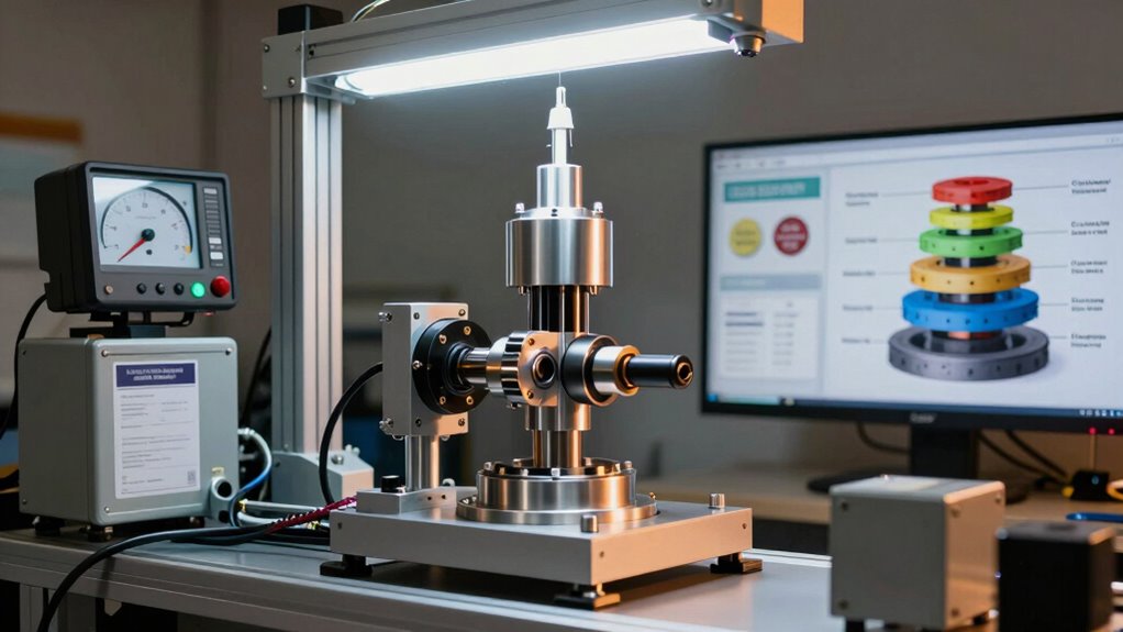
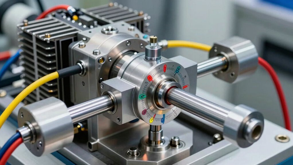
Load Cell Calibration: From Known Weights to Verified Readings
Every dynamometer relies fundamentally on the accuracy of its load cells, the sensors that convert mechanical force into measurable electrical signals. These critical components demand rigorous calibration to guarantee reliable performance data across all vehicle testing scenarios.
Preparation and Setup
Before beginning calibration, technicians must examine mechanical systems and load cell installations for cable excess or misalignment. Even load distribution among multiple load cells is essential, requiring shims if readings differ by more than 10%.
The complete system must be zeroed prior to applying any loads. Regular calibration is needed due to deterioration from use, mistreatment, and environmental factors that compromise measurement reliability over time. Our cutting-edge software solutions help monitor these factors continuously to maintain optimal dynamometer performance.
Deadweight Calibration Process
Using standard weights as calibration tools, operators load vessels evenly in incremental steps: 10%, 20%, 40%, 60%, 80%, and 100% of capacity.
This systematic approach achieves 0.25% full scale accuracy, establishing traceability to national standards and guaranteeing professional-grade measurement integrity for all dynamometer load cell types.
Apply ISO 376 and ASTM E74 Protocols to Your Load Cells
To guarantee load cells deliver measurement data that meets international standards, technicians must apply rigorous calibration protocols recognised globally in engineering and metrology.
ISO calibration and ASTM standards represent the backbone of force verification, establishing accuracy classes and measurement uncertainty limits that maintain load cell performance remains consistent and traceable. Regular calibration intervals prevent accumulated strain gauge drift and other deviations that compromise long-term measurement reliability.
ISO calibration and ASTM standards establish accuracy classes and measurement uncertainty limits ensuring load cell performance remains consistent and traceable.
ISO 376 specifies static uniaxial verification methods, classifying force transducers into precision tiers like Class 00, while ASTM E74 offers complementary flexibility for low-force testing points below 2% of maximum capacity.
Both protocols demand uniform loading sequences across eight to twelve force points, maintained temperature stability within ±1°C, and synchronisation between reference and measurement instruments. Through advanced testing methodologies, these calibration procedures ensure that dynamometer systems maintain the precision necessary for reliable performance assessment.
Applying these structures guarantees calibration traceability to international units, converting raw sensor data into verified, scientifically valid measurements that professionals can trust for critical automotive diagnostics and performance analysis.
While ISO 376 and ASTM E74 protocols establish the calibration structure and accuracy requirements, the actual execution of those standards depends on controlled, repeatable force application.
Standardised force application guarantees uniform results across all dynamometer testing cycles. Operators must apply loads at precise calibration distances on the moment arm, maintaining consistent horizontal positioning for accurate torque conversion. This methodical approach eliminates variables that compromise data integrity. Our precision testing services ensure that all calibration procedures meet these exacting standards.
The load sequencing process requires at least 30 force applications representing every 10% of the calibration range. Weights must be spaced equally, with partial load removal before applying larger increments. This systematic progression—reducing from 7 kilonewtons to 4 kilonewtons before advancing to 14 kilonewtons—prevents mechanical drift and guarantees repeatable measurements. Multiple series of efforts applied with transducer rotated help mitigate interference effects caused by inherent imperfections in the calibration bench.
Returning applied force to zero between applications reinforces consistency. By adhering to these controlled procedures, dynamometer operators achieve the measurement reliability essential for professional automotive diagnostics and performance validation.
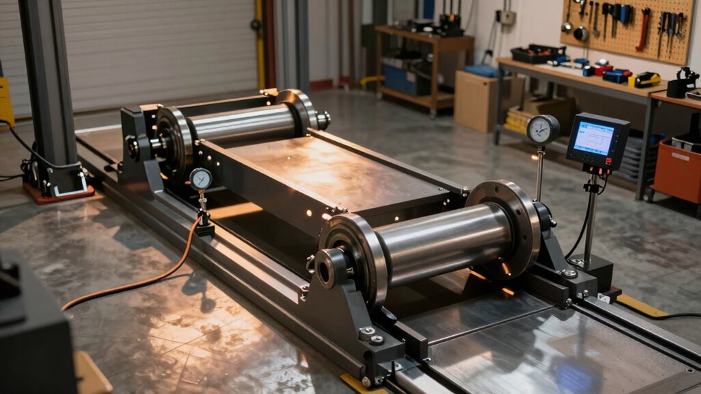
Fix Roller Drift With Inertia Calibration
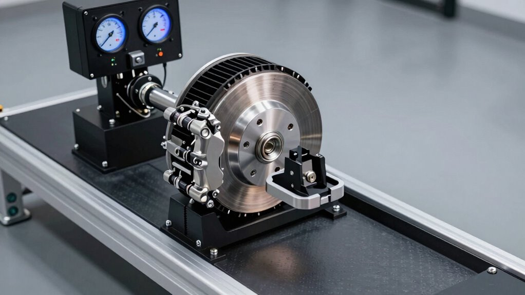
Roller drift represents one of the most common sources of measurement error in dynamometer systems, yet it remains correctable through precise inertia calibration. This phenomenon occurs when rollers decelerate unevenly, skewing power and torque readings.
Roller drift causes uneven deceleration in dynamometer rollers, creating measurement errors in power and torque readings that precise inertia calibration can correct.
The calibration process begins with preparation: set roller diameters accurately, disable load cells on braked dynamometers, and establish an initial inertia value of 1kgm² for the loss model. Technicians tape a thin rope to the roller for non-permanent disconnection during the slowdown phase. Correct inertia values should be calculated using the equation: correct inertia = current inertia * real power / measured power to ensure measurement accuracy. Our expert calibration techniques guarantee precise adjustments throughout this critical phase.
During the drift measurement run, operators unwind the rope at the marked spot, allowing rollers to decelerate freely until complete cessation. The software calculates the loss model automatically, enabling precise roller inertia adjustment through the settings menu.
This systematic approach eliminates drift errors, ensuring consistent, reliable test results across all future measurements.
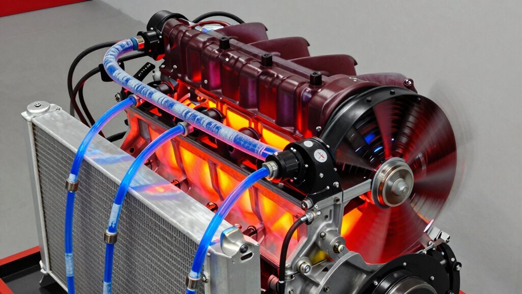
Adjust Motor Dyno Torque Using the Potentiometer Method
Because torque measurement accuracy forms the foundation of reliable dynamometer testing, the potentiometer method provides technicians with a systematic approach to calibrate motor dyno systems with precision.
The potentiometer adjusts the torque signal gain by converting arm deflection into proportional analogue voltage. Technicians enter the calculated torque value into software, then activate the adjustment function to recalibrate the controller and matching parameters. This process guarantees measured torque aligns with reference standards. The Performance Monitor block enables visualisation of steady-state and dynamic results to validate calibration effectiveness across various operating conditions.
After potentiometer adjustments are complete, operators remove calibration weights and verify zero torque conditions. The system resizes parameters for motor specifications, targeting maximum power and DC link voltage levels. Our proactive system monitoring ensures your dynamometer maintains calibration integrity between scheduled maintenance intervals.
Testing every six months maintains repeatable results across speed, torque, and power measurements, confirming long-term accuracy and system reliability.
Maintaining dynamometer accuracy requires a two-tier approach: weekly performance verification using coastdown testing to catch potential drift, and monthly full calibration to guarantee measurement integrity across all inertia settings.
These procedures establish clear tolerance bands for coastdown times and horsepower measurements, with documented adjustments serving as critical reference points for regulatory compliance and repeatability.
Proper documentation and traceability throughout both processes create an auditable record that protects operations, validates test results, and demonstrates adherence to federal standards.
Certification in dynamometer technology ensures professionals understand these calibration protocols and can maintain the operational mastery necessary for reliable results across all testing scenarios.
How can operators guarantee their dynamometer systems deliver consistent, reliable measurements from one testing session to the next? Federal regulations mandate minimum weekly performance verification to maintain operational standards and ascertain measurement accuracy without requiring full monthly calibration when equipment remains within acceptable tolerances.
Professional operators follow a systematic approach to verify performance consistency:
- Document torque sensor readings against calibration weight references
- Monitor exhaust back-pressure and airflow patterns for environmental stability
- Verify engine cooling system functionality to prevent thermal inconsistencies
- Record ECU data including throttle position, injector duty cycle, and fuel trim values
- Generate before-and-after performance charts establishing baseline horsepower and torque measurements
These verification procedures, typically completed in 10-15 minutes, identify measurement drift early.
Documented results demonstrate compliance with federal standards while enabling operators to detect anomalies between scheduled maintenance intervals. For systems that drift beyond acceptable tolerances, custom software solutions can be implemented to realign your dynamometer with specific testing requirements and restore precision performance.
Monthly Recalibration Protocol Requirements
While weekly performance verification catches drift early and confirms equipment remains within acceptable tolerances, monthly calibration establishes the definitive accuracy baseline for dynamometer systems.
Federal regulations mandate monthly recalibration for all dynamometer types used in emissions testing and quality control applications.
During monthly recalibration, technicians verify load cell accuracy, voltage gains, and dead bands according to established parameters.
All measurement points must fall within 0.3 horsepower of the calibration line, with slope agreement maintained within 3% of previous readings.
Regulatory compliance documentation demonstrates adherence to this schedule, ensuring your facility meets industry standards.
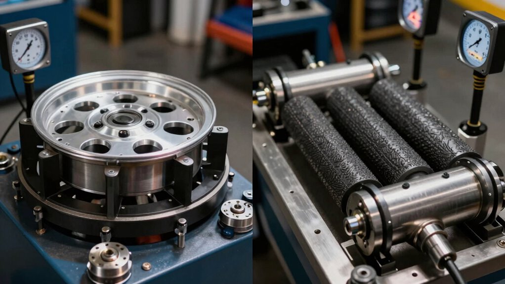
Three-point inertia checks on standard test masses verify calibration curve consistency across the entire operating range, confirming system reliability and measurement integrity for ongoing operations.
Regular software updates enhance calibration performance and ensure your dynamometer maintains cutting-edge accuracy standards throughout its operational lifecycle.
Documentation and Traceability Standards
Documentation and traceability form the backbone of any credible dynamometer operation, creating an auditable record that demonstrates equipment reliability and measurement integrity to regulators, customers, and internal stakeholders alike.
Thorough documentation accuracy guarantees compliance with federal regulations and industry standards. Organisations implementing rigorous traceability processes establish confidence in their testing results:
- Record environmental conditions including temperature, humidity, and atmospheric pressure at test time
- Document correction standards applied, preferably SAE J1349, with factors typically ranging from 0.95 to 1.05
- Maintain NIST-traceable calibrations compliant with ISO 9001 and ISO/IEC 17025:2017 accreditation
- Provide both corrected and uncorrected power values for thorough analysis
- Retain calibration certificates in accessible online databases for audit support
These systematic approaches enable professionals to demonstrate measurement credibility while building client confidence through transparent, verifiable testing protocols. Real-time performance evaluations enhance the reliability and accuracy of documented results across all testing conditions.
What to Do If Calibration Values Still Don’t Match?
When calibration values persistently deviate from expected results, operators should execute a repeat force application series, systematically reapplying known loads to the dynamometer while monitoring raw sensor output for consistency and stability.
This repetitive testing reveals whether discrepancies stem from transducer misalignment, load cell positioning errors, or intermittent connection issues that single-pass calibrations might overlook.
Verifying transducer alignment settings—ensuring load cells are properly oriented and mechanically centred—often resolves stubborn calibration failures that resist standard troubleshooting protocols.
Repeat Force Application Series
Should initial calibration efforts fail to produce accurate readings, the repeat force application series offers a systematic approach to diagnose and resolve persistent discrepancies. This methodology employs incremental force application through cyclical testing, ensuring precision across unlimited force ranges.
Key Protocol Elements:
- Apply force incrementally, adding primary dynamometer readings to previous measurements each cycle.
- Continue until reaching the test dynamometer’s peak rated force capacity.
- Maintain hollow cylinder movement to relieve force on the primary unit while preserving test unit pressure.
- Never exceed primary dynamometer error margins through progressive force increases.
- Repeat the complete cycle series to verify consistency and identify anomalies.
This structured approach systematically isolates calibration issues. Utilising quality assurance processes throughout the calibration procedure ensures that any remaining discrepancies can be confidently attributed to specific equipment or procedural factors rather than overlooked manufacturing defects.
Technicians can confidently identify whether discrepancies stem from equipment malfunction or procedural error, enabling targeted corrective action and restoring measurement accuracy.
Verify Transducer Alignment Settings
After completing the repeat force application series, technicians may reveal that calibration discrepancies persist despite systematic testing cycles. When standard adjustments fail to resolve misalignment issues, the transducer centre itself requires careful inspection against the force application axis.
Identifying Alignment Problems
Imperfect benches introduce interfering torque components that compromise signal accuracy. Technicians should rotate the transducer in 90°, 120°, or 180° increments to detect alignment sensitivity patterns.
Consistent signal variations across rotations indicate torque alignment problems rather than electronic faults.
Corrective Action
Rigorous mechanical reassembly centres the transducer on the force axis, minimising misalignment effects. The horizontal calibration beam position must guarantee zero torque readings within one least significant digit.
Once repositioned, repeat the full calibration sequence using known weight standards for verification.