Meta Description:
Most engineers get force and torque backward—and it’s costing them. These two forces operate in completely different dimensions, yet one misconception about their relationship can tank your machine’s efficiency by half. Discover why treating them as interchangeable will sabotage your next project, and learn the counterintuitive truth that separates elite mechanics from the rest.
What’s the Difference Between Force and Torque?
Two fundamental concepts govern how objects move and rotate in the physical world: force and torque.
Force represents a push or pull measured in newtons, creating linear motion and acceleration along a straight path. Torque, measured in newton-metres, produces rotational motion around a fixed axis.
Force creates linear motion through push or pull, while torque produces rotational motion around a fixed axis.
The key distinction lies in their applications. Force applications directly change an object’s velocity or direction through linear acceleration, following the equation F = ma.
Torque applications rotate objects by applying force at a distance from the rotation axis, calculated as τ = F × r × sin(θ). Both force and torque are vector quantities that possess magnitude and direction.
Understanding these differences proves essential in automotive diagnostics and engineering. Professionals utilise force and torque principles to measure vehicle performance accurately through comprehensive data collection across a range of conditions, ensuring precision in testing protocols and providing reliable, repeatable results that drive innovation forward.
Force Produces Linear Motion
While torque governs rotational behaviour around a fixed axis, force operates through an entirely different mechanism to create straightforward, predictable motion along a single path. According to Newton’s second law, unbalanced force produces linear acceleration, fundamentally altering an object’s velocity in one dimension. This relationship, expressed as F = ma, demonstrates how applied force directly determines acceleration magnitude.
Understanding linear motion requires proficiency in kinematic equations, which predict position and velocity under constant force conditions. These four fundamental equations—involving initial velocity, acceleration, time, and displacement—enable engineers to model real-world scenarios with precision. In free fall scenarios, gravitational acceleration remains constant at approximately 9.81 m/s² downwards, allowing for consistent predictions of motion under gravity alone.
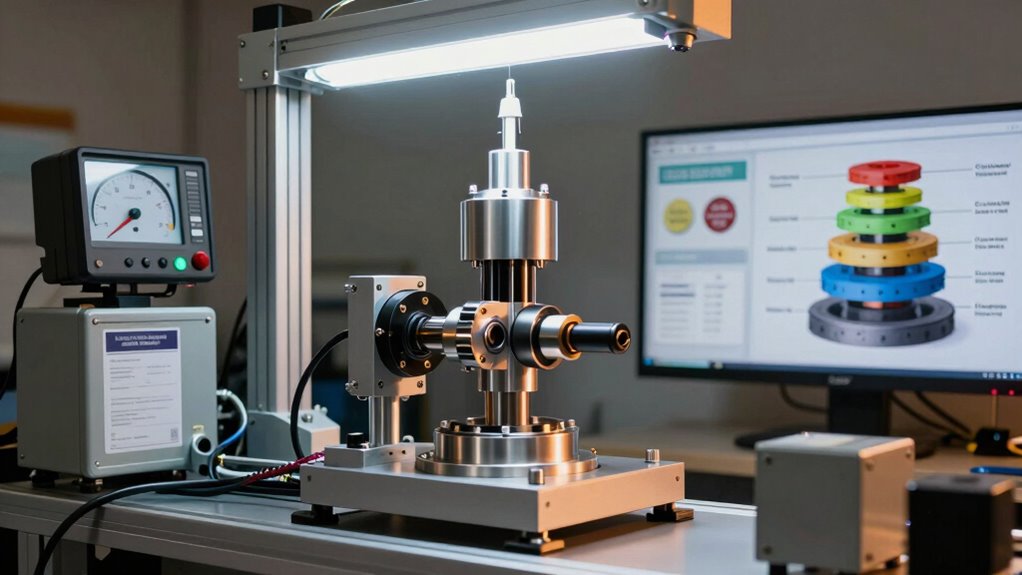
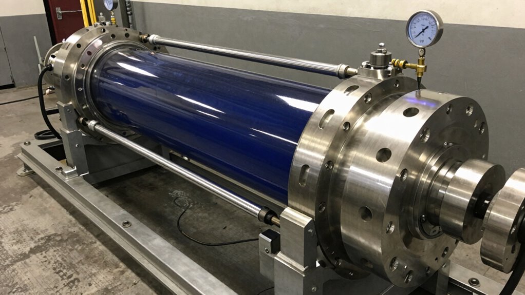
Whether analysing vehicle performance data or calculating brake distances, kinetic equations provide the mathematical structure professionals rely on. Advanced dynamometer systems like those from precision testing equipment providers enhance the accuracy of these measurements in controlled environments.
Force-driven linear motion underlies countless automotive applications, from chassis dynamometer testing to performance measurement protocols that Hyper Power specialists employ daily.
Torque Produces Rotational Motion
Unlike force, which accelerates an object in a straight line, torque initiates rotation around a central axis by applying a twisting motion rather than a linear push.
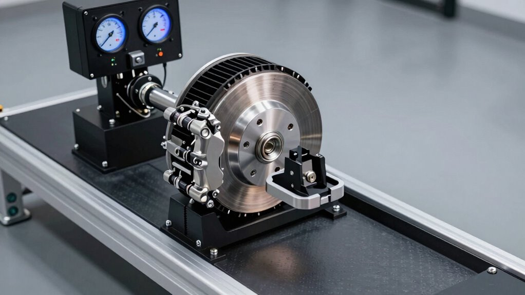
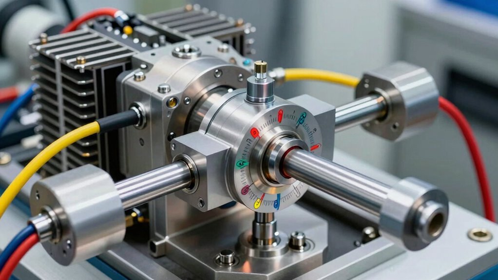
The magnitude of this rotational effect depends critically on the lever arm distance—the perpendicular span from the axis to where the force is applied—meaning that even modest force can produce substantial rotation when applied at greater distances. This relationship is mathematically expressed as τ = rF sin(θ), where the angle between vectors significantly influences the resulting torque value. Modern dynamometer systems utilise this principle to accurately measure and test rotational performance across various vehicle types.
Comprehending this distinction between twist and thrust proves essential for engineers and technicians optimising vehicle performance, as both the force magnitude and its positioning relative to the rotation axis determine the angular acceleration an engine or drivetrain component will experience.
Angular Acceleration Around Axis
How does torque actually change the rotational motion of an object? Torque directly produces angular acceleration through the fundamental equation τ = Iα, where rotational inertia (I) represents how mass distributes around the rotation axis.
Greater torque generates proportionally greater angular acceleration, similar to how force produces linear acceleration in Newton’s Second Law.
Angular momentum changes only when external torque acts upon it. Objects rotating at constant velocity maintain their motion without additional torque input. The derivative of torque with respect to time, known as rotatum, represents successive changes in rotational force application. Advanced diagnostics through real-time performance evaluations enable precise measurement of these rotational dynamics during vehicle testing.
The relationship between torque and angular acceleration depends critically on rotational inertia—objects with mass concentrated far from the axis resist acceleration more than those with centralised mass.
Understanding this principle proves essential for dynamometer operations, where precise torque measurement reveals how vehicles respond to loading conditions and performance modifications.
Lever Arm Distance Matters
A door hinge serves as an intuitive entry point for grasping why the distance from a pivot point fundamentally determines how effectively force creates rotation. The lever arm—that perpendicular distance from the pivot to where force acts—directly governs torque efficiency and rotational capability.
Understanding this relationship reveals critical principles:
- Distance amplification: Pushing a door near its edge generates substantially more rotational force than pushing near the hinge, demonstrating how lever arm length directly multiplies torque output.
- Perpendicular positioning: Maximum torque occurs when force acts at 90 degrees to the lever arm; angled force reduces the effective lever arm and diminishes rotational power.
- Practical application: Industrial equipment operators achieve superior performance by enhancing force application distance, ensuring investments in machinery deliver measurable results. Precision torque measurement through quality assurance processes validates that performance gains are accurately quantified and reproducible. When the angle between the force vector and lever arm deviates from perpendicular, zero lever arm results regardless of the magnitude of force applied.
Professionals who grasp lever arm importance reveal superior torque efficiency, translating mechanical advantage into tangible performance gains across automotive, industrial, and agricultural applications.
Twist Versus Linear Push
When force is applied perpendicular to a lever arm, it creates torque—a rotational force fundamentally different from the linear pushing or pulling motion that moves objects in straight lines.
Force produces translational movement, moving an object from one location to another in a direct path. Torque, by contrast, generates a twisting force that causes rotational activity around a fixed axis or pivot point.
The distinction matters practically: pushing a door produces linear motion if applied at the pivot, but applying that same force perpendicular to the door’s surface creates rotation. This twisting force represents torque’s essence.
Angular velocity increases when torque is applied, similar to how linear velocity increases with force. Comprehending this fundamental difference enables professionals to predict mechanical behaviour accurately and enhance equipment performance, whether analysing engine output or testing vehicle drivetrains. Understanding these principles is essential when utilising advanced diagnostic tools to evaluate system performance and optimise dynamometer testing results.
Why Distance Matters to Torque
Comprehending the relationship between distance and torque reveals a fundamental principle that shapes how engineers design everything from automotive drivetrains to mechanical systems in industrial settings.
The lever arm—the perpendicular distance from the rotation axis to the force line of action—directly determines torque magnitude and effectiveness.
The perpendicular distance from the rotation axis directly determines torque magnitude and effectiveness in mechanical systems.
Distance amplifies torque production in three critical ways:
- Linear Proportionality: Torque increases proportionally with greater separation from the pivot point, allowing engineers to achieve stronger rotational effects with identical force magnitudes.
- Lever Arm Enhancement: Maximum torque occurs at 90-degree angles between the position vector and applied force, establishing ideal torque application geometry.
- Practical Efficiency: Increased distance enables smaller forces to generate substantial rotational power, reducing mechanical strain and improving system performance.
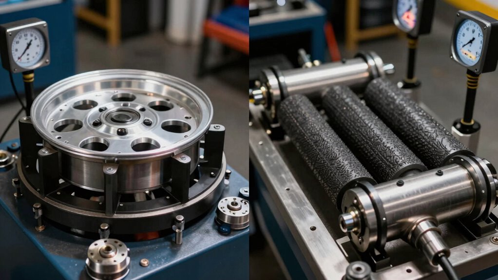
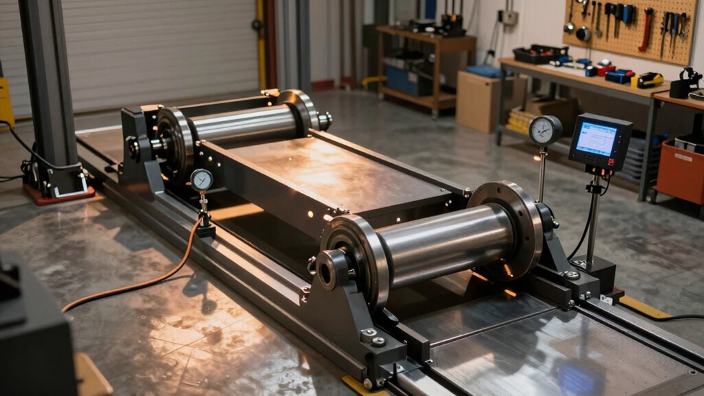
This principle fundamentally influences how Hyper Power’s dynamometer systems measure and simulate real-world engine performance across diverse testing protocols, with advanced integration capabilities enabling precise replication of these mechanical principles in controlled laboratory environments.
When Force Produces No Torque
Just as distance amplifies rotational effects, the direction of applied force determines whether rotation occurs at all. A parallel force aligned with the position vector generates zero torque, despite substantial force magnitude. When force direction matches the radius vector, the perpendicular component vanishes entirely, eliminating rotational motion.
The mathematical relationship confirms this principle: torque equals force multiplied by the perpendicular distance from the pivot point. At zero degrees of alignment, this perpendicular distance becomes zero, resulting in zero torque. Pushing a door directly toward its hinge exemplifies this concept—the door remains stationary rather than rotating.
Forces applied directly at the pivot point similarly produce no rotational effect. These parallel force scenarios contribute exclusively to linear motion, preserving rotational equilibrium regardless of force intensity.
Force and Torque in Action
Rotational motion permeates everyday life, from the simple mechanics of opening a door to the complex engineering of automobile engines. This demonstrates how force applied at a distance generates the torque necessary for movement and power transfer.
Understanding torque in practical applications reveals its fundamental role across industries:
Understanding torque’s practical applications reveals its fundamental role in converting applied force into rotational work across industries.
- Seesaw mechanics illustrate basic torque principles, where opposing forces at different distances from a pivot point create competing rotational effects. Heavier loads descend as greater torque overcomes balance.
- Bicycle pedalling transfers leg force through pedals positioned at a distance from the axle, generating torque that rotates wheels via chain and gears. This enables efficient power transfer.
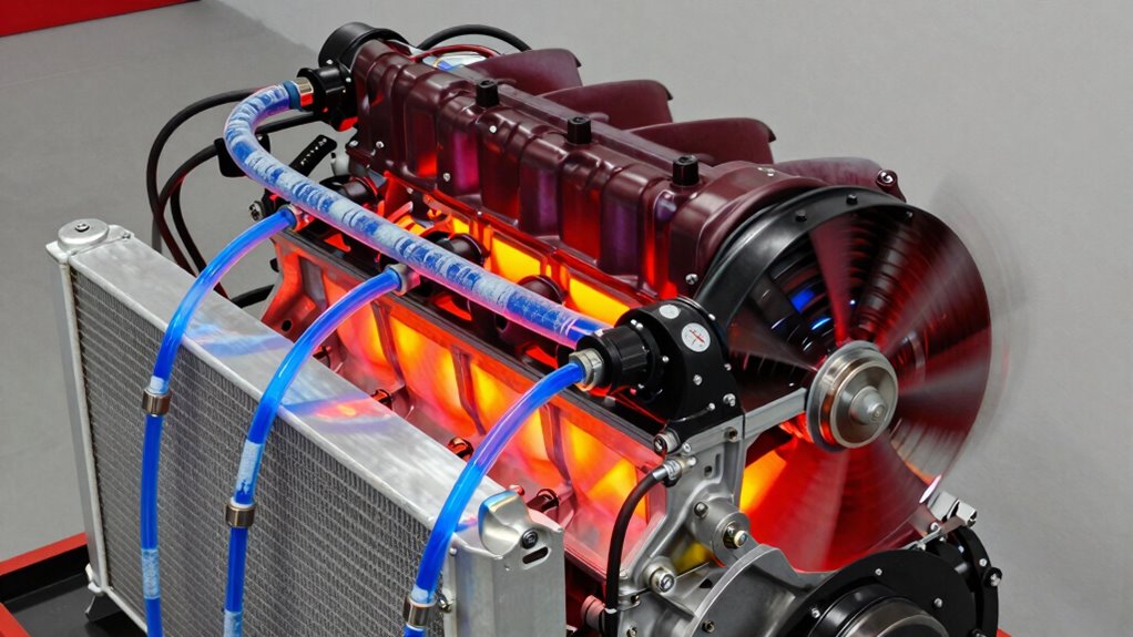
- Engine performance relies on consistent torque output to rotate components, transferring rotational power that moves vehicles and operates machinery.
These everyday examples demonstrate torque’s universal importance in converting applied force into practical rotational work.
Equations and Units Explained
The mathematical foundation underlying force and torque separates intuitive comprehension from precise measurement, enabling engineers and technicians to quantify mechanical behaviour with scientific accuracy.
Force Definition and Calculation****
Force, defined through Newton’s second law as F = ma, represents the direct relationship between mass and linear acceleration. Measured in newtons (N), where 1 N equals 1 kg·m/s², force remains independent of position or rotation axis, maintaining consistency across all applications.
Torque Definition and Measurement
Torque definition emerges from the vector cross product τ = r × F, with magnitude expressed as τ = rF sin θ. Measured in newton-metres (N·m), torque incorporates an essential length factor, distinguishing it fundamentally from force while maintaining SI unit consistency.
Practical Application
Understanding these distinctions enables professionals to properly analyse rotational versus translational motion, ensuring accurate performance diagnostics and engineering solutions.
Key Takeaways: When to Use Each
Comprehending when to apply force versus torque depends on the type of motion required, whether linear or rotational.
Linear tasks—such as braking a vehicle or pushing materials in a press—demand force calculations, while rotational applications like engine performance or bolt tightening require torque analysis.
Recognising which principle governs a specific mechanical situation guarantees proper equipment selection, accurate measurements, and ideal operational outcomes.
Choosing Force Over Torque
Distinguishing between force and torque measurements determines whether testing equipment delivers accurate, actionable data for a given application.
Linear force and rotational force represent fundamentally different physical phenomena, requiring distinct sensor technologies and measurement strategies.
Engineers select force sensors when applications involve straight-line push-pull motion without rotation:
- Static load applications rely on force sensors for weight measurement, compression monitoring, and tension analysis in rigging systems.
- Non-rotating scenarios demand force transducers, such as check-weighers on production lines and flange compression sensors handling high stiffness loads.
- Multi-directional precision benefits from 3-axis force sensors when linear accuracy proves critical without twisting components.
Force sensors excel in applications where no pivot point or rotational component exists.
Torque transducers, conversely, risk axial force overload when misapplied to linear scenarios.
Selecting the appropriate measurement technology guarantees reliable, repeatable data collection essential for professional automotive diagnostics and industrial testing protocols.
Rotational Versus Linear Motion
When equipment operates on spinning shafts, wheels, or engine components, rotational motion principles govern how forces translate into measurable output, whereas linear motion applies to systems moving along straight paths without rotation. Grasping this distinction proves essential for technicians working with dynamometer systems and automotive performance equipment.
Rotational mechanics describes spinning bodies using angular quantities like angular velocity and torque, where all points on a shaft rotate uniformly despite varying linear speeds at different radii. Linear mechanics, conversely, measures straight-path movement through displacement and force, making it ideal for analysing components moving without rotation.
Professional technicians recognise that most automotive applications combine both principles. Engine testing requires rotational mechanics knowledge for shaft analysis, while drivetrain efficiency assessments incorporate linear mechanics principles, ensuring thorough performance evaluation and accurate diagnostic results. Pursuing dynamometer professional certification ensures technicians maintain mastery of these critical measurement principles and stay current with industry advancements.