Meta Description:
Most mechanics get roller-to-hub conversions wrong, and it costs thousands in repairs. One misstep in bearing adjustment or torque specifications transforms a performance upgrade into catastrophic drivetrain failure. This guide exposes the exact installation protocols that separate thriving conversions from expensive disasters, revealing why precision matters more than experience alone.
The choice between tapered roller bearings and ball bearing hubs represents a fundamental engineering decision that directly impacts vehicle durability and performance.
The choice between tapered roller bearings and ball bearing hubs fundamentally shapes vehicle durability and performance outcomes.
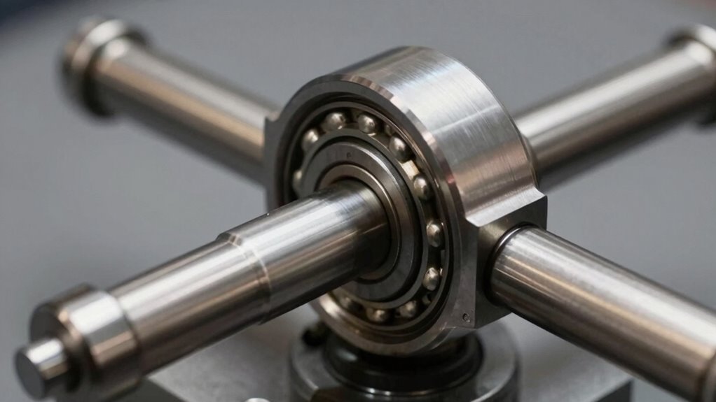
Tapered roller bearings excel in load distribution, their cone-shaped design creating a wider contact patch that disperses forces evenly across the bearing surface. This geometry outperforms the point-contact limitations of ball bearings, particularly under combined axial and radial stresses.
For lorries, SUVs, and heavy-duty vehicles, tapered designs prove superior. The larger contact area between tapered rollers and rings supports substantially higher loads, while ball bearings struggle with axial forces. Tapered roller bearings also demonstrate high speed stability, making them particularly reliable during motorway operation and emergency manoeuvres.
Furthermore, tapered bearing types withstand shock loads and rough terrain with greater resilience, resisting contamination and misalignment better than their spherical counterparts. This load distribution advantage translates directly to extended service life and reduced maintenance costs for professional workshops managing demanding applications.
Converting from roller bearings to hub assemblies demands specific mechanical equipment and precision instruments that form the foundation of any successful workshop operation.
A hydraulic press serves as the cornerstone tool, providing the controlled force necessary to safely remove and install bearing components without damaging critical surfaces, while precision torque and socket tools guarantee that every fastener meets exact specifications throughout the conversion process. Manual locking hub conversion kits offer reduced drivetrain drag that can improve fuel economy during both on-road and off-road applications.
These essential instruments, combined with proper measurement devices, allow technicians to execute conversions with the repeatability and accuracy that modern vehicle performance demands.
Essential Hydraulic Press Equipment
Building a functional hydraulic press conversion requires comprehension of four critical component categories: the power source, the working cylinders, the connecting systems, and the control mechanisms.
Power Source and Cylinders
Electric hydraulic pumps replace manual operation, with 2HP units capable of generating 10,000 PSI for high-tonnage applications. The VersaPress system offers a 2.0 HP Electric Hydraulic Power Unit specifically designed for Harbour Freight press compatibility and stand-alone operation.
Double-acting cylinders enable both press and retract functions, accommodating various capacity considerations from 20-ton to 50-ton configurations.
Connections and Controls
Custom hoses with metric fittings like M14 taps connect components modularly, supporting quick-disconnect systems for flexibility.
Foot pedal controls provide hands-free operation, while release valves enable precise pressure management and safety measures throughout hydraulic systems.
Proper mounting techniques using steel plates guarantee stability during press conversions.
Once hydraulic systems are properly installed and calibrated, attention shifts to the fastening components that secure critical assemblies within the conversion setup.
Precision tools are essential for reliable performance, ensuring that bolts, lugs, and fasteners meet exact specifications. Torque accuracy ranges from ±2-4% on professional equipment, with dial torque wrenches providing ±2% precision across clockwise and counterclockwise applications. Regular calibration services are recommended at least once or twice a year to maintain accuracy and ensure consistent performance. Partnering with a technical support team ensures your tools remain properly maintained and calibrated for optimal results.
Drive sizes matter greatly. The 1/2″ drive handles most automotive applications, providing 80-100 ft-lbs for lug nuts and general maintenance.
For heavier work, 3/4″ drives manage 100-600 ft-lbs on trucks and industrial components. Digital and dial variants offer superior accuracy compared to click types, making them ideal for engine rebuilds and critical assemblies where repeatability determines success.
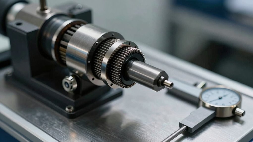
Tapered Roller Bearing Upgrade Parts Checklist
Since upgrading to tapered roller bearings represents a meaningful investment in steering performance and durability, selecting the correct components requires careful attention to specification details and assembly requirements.
Professionals building conversion kits should verify all bearing types and confirm load capacity ratings match their application demands.
Essential components for a complete upgrade include:
- Matched bearing sets in appropriate configurations (X, O, or tandem) with pre-matched intermediate ring geometry
- Quality seals and dust caps designed to prevent contamination during operation
- DIN 51825-compliant grease for proper lubrication at startup
Inspecting shafts, races, and housing alignment before assembly prevents premature wear. Both top and bottom races must be installed correctly to ensure the bearing seats properly within the neck.
Selecting ready-to-fit matched sets eliminates assembly complications, ensuring installations meet precision standards that justify the investment.
How to Safely Remove Your Old Hub Assembly
Before extracting the hub assembly, technicians must address the cotter pin and fasteners securing the spindle, as improper removal can damage critical seals and compromise component integrity.
The spindle nut extraction method requires careful attention to prevent harm to the hub outer seal, with a 15 mm socket recommended for connection bolt removal and lockwasher tabs straightened prior to outer nut loosening.
Proper technique during these initial steps establishes the foundation for safe hub removal and protects warranty coverage on replacement components.
Subheading Discussion Points
Hub assembly removal demands methodical preparation and the right tools to prevent damage to brake systems, CV joints, and suspension components. Comprehending proper techniques guarantees success while minimising installation challenges during reassembly.
The removal process involves three critical phases:
- Preparation and access—securing the vehicle, removing wheels, disconnecting brake calipers, and protecting CV boots with landing pads.
- Tool assembly—attaching hub pullers to lug nut holes and securing the slide hammer mechanism firmly.
- Controlled extraction—applying gradual pressure through turning the axle shaft and using slide hammer strikes to break the hub free.
Technicians must work methodically, avoiding direct hammering and instead employing puller tools for controlled force application.
Hub compatibility concerns require inspecting the knuckle assembly for damage before proceeding with new hub installation, verifying proper fit and function.
Cotter Pin Removal Technique
Extracting a cotter pin requires patience, proper preparation, and an understanding of the forces at work on this small but critical fastener. Technicians should first wipe away grease, apply penetrating oil, and secure the assembly firmly in a vice or workbench.
Removal Techniques
The needle-nose pliers method involves gripping and straightening the split ends, then pulling the pin straight out.
For stubborn pins, a C-clamp with socket provides consistent pressure under lubrication.
Impact techniques using a hammer and steel bar work effectively when applied carefully with a wood block underneath for support.
Critical Safety Measures
Avoid hammering directly on the pin to prevent bearing stress.
Always inspect the pin for reuse, replacing damaged units with part #165649.
Testing the arm for rocking afterwards confirms successful removal.
Once the cotter pin has been removed and the assembly is secure, attention shifts to the spindle nut itself, the component that holds the entire hub system in place.
Proper Spindle Nut Techniques
The spindle nut extraction process requires precision and the correct extraction tools to avoid damage. Technicians should follow these essential steps:
- Hold the driveside locknut firmly with one spanner while simultaneously undoing the non-driveside cone with another spanner.
- Wind off the non-driveside cone by hand after initial loosening, then remove the locking nut and spacer.
- Document the order of all locknuts and spacers using photographs for accurate reassembly.
Once removed, the axle can be carefully extracted from the hub. This methodical approach guarantees component preservation and successful hub conversion completion.
Installing Your New Hub on the Knuckle
Several critical preparatory steps must be completed before the new hub assembly can be properly installed on the steering knuckle, as rushing through this phase introduces the risk of premature bearing failure and component damage.
Proper cleaning procedures guarantee peak performance and longevity of your investment.
Begin with thorough cleaning procedures on the steering knuckle’s inner mounting surfaces using a steel scratch brush to remove burrs, corrosion, and loose metal.
Apply anti-seize compound to the knuckle to prevent future seizing between components.
Carefully guide the hub assembly onto the CV shaft and into the steering knuckle, maintaining precise alignment throughout.
Never force components or use hammers during installation.
Verify correct axle shaft spline positioning before proceeding.
Follow these installation tips to achieve professional results and protect your equipment investment.
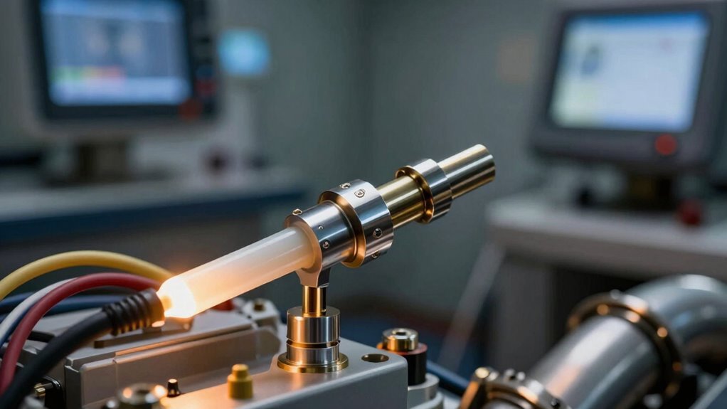
Packing and Lubricating Tapered Roller Bearings
Proper lubrication represents one of the most critical steps in bearing assembly, as inadequate or improper grease application directly leads to premature failure, increased friction, and costly component replacement.
Technicians must select appropriate grease specifications and employ correct lubrication techniques to guarantee bearing longevity.
Grease Application Methods
Professional workshops employ two primary approaches:
- Hand packing, where grease is manually distributed into the bearing cavity for even coverage.
- Mechanical grease packers that use downward pressure on a conical retainer to force grease between rollers and cone components.
- Full-pack lubrication, requiring additional grease injection after cartridge closure.
Lubricant Selection
Lithium-based grease with extreme pressure additives meeting NLGI No.2 specifications suits most applications.
Operating temperatures between 0°C to 80°C support this selection, providing reliable performance across diverse workshop environments and seasonal conditions.
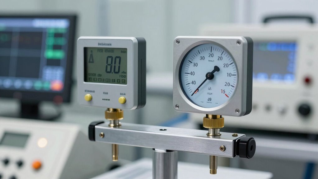
Adjusting End Float With Shim Selection
After grease has been properly applied and the bearing is seated, technicians face the next critical assembly step: controlling the axial clearance, or end float, that determines how freely the bearing operates under load.
Proper shim types and tolerance adjustment prevent excessive noise, premature wear, and friction-induced heat that compromises bearing longevity.
The SET-RIGHT method employs shims to correct end play by compensating for manufacturing tolerances. Using the formula shim = A + B + C + D – E – F, technicians target a mean setting of 0.108 mm.
This precision approach achieves the ideal 0.001 to 0.005-inch range, ensuring balanced preload.
A dial indicator mounted near the hub verifies end float by measuring total spindle movement when pushed and pulled.
This verification confirms proper tolerance adjustment before final locking.
Torque Sequencing: Stub Axle Through Hub Lock
The assembly process for stub axle and hub lock systems demands precise torque application in a carefully orchestrated sequence, where thread direction, pretightening progression, and final locking mechanisms work together to establish a bearing preload that resists loosening during vehicle operation.
Technicians must follow three critical torque specifications:
- Pretighten the inner spindle nut to 150 Nm while rotating the hub unit five turns.
- Apply final tightening by one graduation mark (30°) after pretightening completes.
- Torque the outer nut to 100-175 lb-ft while securing the inner nut at 150 Nm reference.
Thread direction varies by axle position, with left-hand threads marked by milled grooves on the collar.
Locking mechanisms—slip-on lock discs, cotter pins, or tang washers—prevent rotational movement under load, ensuring consistent performance throughout the vehicle’s service life.
Filling Your Hub With Oil and Settling Bearings
Hub lubrication stands as a fundamental maintenance procedure that directly impacts bearing longevity and vehicle safety, requiring methodical preparation and adherence to manufacturer specifications.
Hub lubrication directly impacts bearing longevity and vehicle safety, requiring methodical preparation and manufacturer specification adherence.
Technicians should clean the fill hole area thoroughly, then remove the plug using appropriate tools.
Oil Fill Techniques
Using a clean funnel, pour 80W–90 hypoid gear oil into each hub, adding approximately 1 to 1-1/2 pints per side.
Allow the oil 10 minutes to settle before checking levels, then rotate wheels to distribute lubricant throughout the assembly.
Hub Oil Maintenance
Verify oil reaches the fill line indicator on the hubcap, repeating the filling process if necessary.
Install the fill plug, torquing to 20-25 ft. lbs., and wipe away excess oil.
This systematic hub oil maintenance prevents overfilling and contamination, ensuring ideal bearing performance.
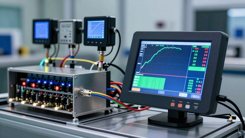
Diagnosing Binding, End Float, and Installation Issues
Proper hub bearing diagnosis requires comprehension of three critical failure modes: binding, end float issues, and installation errors that can compromise vehicle safety and bearing longevity.
Binding Diagnosis
Binding occurs when hub bearings resist rotation after nut tightening without shims. Technicians tighten the stub axle nut until bearings bind to establish an initial adjustment baseline. Excessive preload causes binding; a spin check verifies free rotation post-shim insertion.
Key Diagnostic Points:
- Roller bearing thrust width exceeds ball bearings by 0.069 inches, pushing hubs outboard and causing binding near seal lips.
- Torque-SET method assembles with preload shim packs, measuring rolling torque against charts for binding diagnosis. Utilising advanced dynamometer technology ensures precise measurement of torque specifications and bearing performance characteristics.
- End float adjustment uses shims between outer bearing and distance piece, with proper end play confirmed by shaft free spin.
Professional diagnosis prevents costly bearing failure and guarantees ideal drivetrain efficiency.