Hub Dyno Installation: Critical Space Requirements
Most facilities get hub dyno spacing wrong—and they don’t realise it until equipment fails or maintenance becomes impossible. The difference between a thriving installation and a catastrophic failure often comes down to inches of clearance, cable routing decisions, and pod positioning that facility managers rarely consider upfront. This guide reveals the exact measurements and layout strategies that separate functional installations from expensive disasters.
Do You Need a Pit, or Will a Flat Floor Work?
How much space does a hub dynamometer actually require? The straightforward answer is none—no pit installation is necessary.
Hub dynos operate efficiently on flat floors, eliminating expensive excavation and construction expenses that traditional pit setups demand.
The flat floor advantages are substantial. Facilities lacking dedicated pit space can utilise hub dynamometers immediately, handling both 2WD and 4WD vehicles with consistent performance.
Shock absorbers manage vehicle camber on level surfaces, ensuring reliable measurements across all vehicle types.
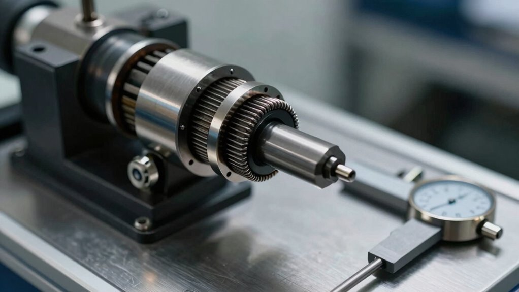
Hub dyno efficiency improves through this simplified approach. Each pod measures just 50 cm × 90 cm × 90 cm, with built-in wheels enabling repositioning without permanent installation. Our cutting-edge software solutions enhance measurement accuracy and data collection during testing operations.
No ground anchorage or strapping is required, allowing operators to establish functional testing stations in garages or non-dedicated areas within minutes. When blocked from accessing technical resources, users can contact site owners via email to resolve security issues and obtain the information needed for equipment specifications.
The footprint requirements for a hub dynamometer system vary greatly based on whether the installation employs a traditional pit or operates on a flat floor, with mobile pod configurations offering additional flexibility for facilities with space constraints.
Comprehending these distinctions allows shop owners to accurately assess their available facility dimensions and select the appropriate system type that aligns with their operational layout.
Each configuration—pit-based, floor-mounted, or mobile—carries specific spatial demands that directly impact installation feasibility and long-term operational efficiency. The dyno can pivot on its centre of gravity, allowing for height adjustments of 40-50 mm that help optimise floor clearance and overall facility utilisation without requiring extensive structural modifications. Professional expert calibration techniques during setup ensure that your dynamometer system delivers accurate measurements regardless of your facility’s configuration.
Pit Versus Floor Installation
Facility layout represents one of the most consequential decisions in dynamometer installation, fundamentally shaping both initial investment and long-term operational flexibility.
Pit installation requires substantial construction investment, while floor advantages offer persuasive alternatives for many workshops.
Key Considerations:
- Cost differential: Pit construction ranges from £5,000 to £25,000, whereas floor installation eliminates these expenses entirely.
- Construction timeline: Floor setups require minimal time, primarily electrical wiring for hub dynos.
- Facility flexibility: Floor-mounted systems enable easier relocation without permanent structural damage.
- Vehicle access: Ramps or four-post lifts serve dual purposes—dyno testing and general shop work.
- Space efficiency: Floor installations accommodate shops without excavation capability or expansion constraints.
Floor advantages extend beyond economics. They provide operational freedom, allowing workshops to modify their facility layout as business needs evolve. Hub dynos mounted directly to wheel hubs avoid tyre roller complications while maintaining portable and minimal installation requirements that preserve shop adaptability. Accessories and parts designed for specific dynamometer models ensure that floor-mounted systems can be customised to address your workshop’s unique testing needs, maximising both performance and versatility.
This flexibility proves essential for growing operations prioritising scalability.
Mobile Pod Space Planning
Mobile dynamometer pods represent a structural shift for workshops operating under spatial constraints, offering capabilities previously reserved for facilities with dedicated pit infrastructure.
The DYNO X DC POD PLUS requires minimal floor space, uncrating and operating on flat surfaces without excavation or permanent installation. This mobile pod advantages approach eliminates infrastructure demands while maintaining high-performance testing.
Capacity Considerations for Your Facility
Pod systems rated at 1,800, 3,500, and 7,200 horsepower accommodate diverse testing needs.
The 2WD 15,000 Series trailer measures 41-42 inches high by 102 inches wide, extending to 26 feet when ramps are set up. Shops can relocate units between locations without floor repairs, providing operational flexibility.
These capacity considerations allow facilities to scale testing capabilities based on current demand and future growth projections. Advanced integration capabilities ensure that your custom dyno system seamlessly operates within your facility’s unique spatial and technical environment.
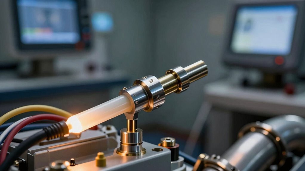
Electrical Setup: Power, Cable Routing, and Cabinet Placement
A properly configured electrical system forms the foundation of safe and reliable hub dynamometer operation, requiring careful attention to voltage specifications, circuit protection, and power distribution across all components.
Hyper Power’s systems accommodate multiple electrical standards—ranging from 110V 60Hz to 240V 50Hz configurations—ensuring compatibility with diverse facility infrastructures, while circuit breakers rated at a minimum of 20A per power supply protect equipment and personnel from electrical faults. During installation, the mainline dyno’s power connections must be established with precision to enable proper computer operation and sensor integration. Our commitment to continuous innovation ensures that electrical configurations incorporate advanced engineering practices for enhanced testing accuracy.
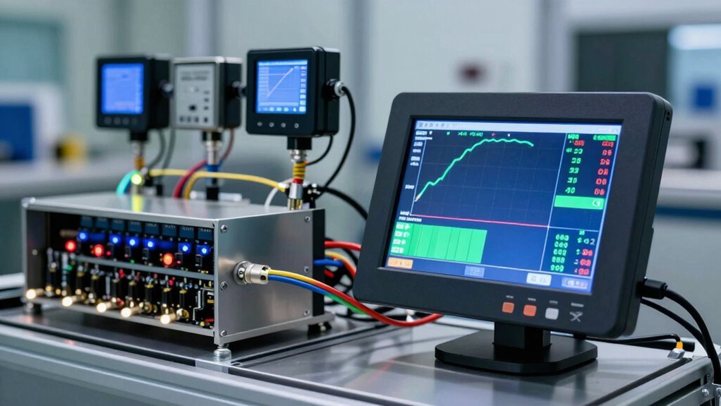
Strategic cabinet placement and methodical cable routing from dyno hubs to the control head unit enhance both accessibility and system performance, allowing operators to establish connections efficiently while maintaining clean signal pathways for accurate data acquisition.
Power Supply Configuration Options
Because hub dynamometers demand consistent, reliable electrical delivery to function safely and accurately, grasping the power supply configuration options becomes crucial during installation planning.
Hyper Power’s systems accommodate flexible voltage requirements across diverse facility infrastructures. Installers select between single-phase or three-phase configurations, with voltage ranges spanning 100-240VAC (single-phase) and 100-415VAC (three-phase), both at 50/60Hz frequencies.
Standard industrial facilities typically operate at 400VAC three-phase, while smaller workshops may employ 220V single-phase supplied at 32A per axle.
Power Supply Options Available:
- Single-phase L-N configuration at 100-240VAC
- Three-phase L-L setup at 100-415VAC
- Standard 400VAC industrial three-phase connection
- 220V/32A per-axle electrical supply
- Cable sizing up to 4mm² for supply connections
Proper voltage selection guarantees ideal brake performance and equipment longevity throughout your facility’s operational lifespan. Comprehensive technical support is available to assist with power supply configuration and calibration during installation.
Cabinet Placement And Routing
Once the power supply configuration is finalised, the physical positioning of the instrument cabinet becomes the next critical installation phase, as its location directly influences both operational efficiency and data accuracy.
Optimal Cabinet Positioning
The cabinet must be installed in a dry, clean location free from excessive vibrations, moisture, and dust.
Avoid positioning the instrument box near water splash zones or areas prone to condensation.
The cabinet’s wheeled design provides mobility, allowing technicians to adjust placement for workflow optimisation and accessibility around the dyno setup.
Proper cabinet placement ensures precise and insightful results during comprehensive testing operations.
Cable Organisation Essentials
Data cables route upwards from the dyno unit’s bottom, with left and right markings ensuring correct connections.
The 12-metre left cable accommodates right-hand drive configurations, routing around the dyno’s rear to reach the cabinet.
Proper cable organisation prevents signal interference and maintains system reliability during testing operations.
Pod Spacing and Wall Clearance: Essential Clearance Distances
Since hub dynamometer pods must function within confined workshop spaces while maintaining operational safety and efficiency, proper spacing and wall clearance become critical installation considerations. The 50 cm x 90 cm x 90 cm pod dimensions require thoughtful placement to accommodate vehicle access and operator movement.
Maintaining adequate clearance around each pod guarantees smooth pod alignment adjustments and prevents interference during setup operations. Hyper Power’s proactive system monitoring services help ensure your installation maintains optimal performance standards throughout its operational life.
Essential Spacing Guidelines:
- Position pods with a minimum 3-foot clearance from workshop walls for cable routing and maintenance access
- Allow 6-foot clearance behind pods for vehicle entry and exit procedures
- Space pods 2 feet apart to enable simultaneous hub adapter adjustments without obstruction
- Reserve 4-foot zones on sides for integrated cooling fans and LED lighting operation
- Maintain clear pathways to cabinet placement for cable management and sensor connections
Proper clearance requirements facilitate efficient workflow, reduce setup time, and promote technician safety throughout testing operations.
D-Hook Spacing: Safe Anchorage Layout for Pit Installations
When hub dynamometer systems are installed in pit configurations, the structural integrity of overhead anchorage points becomes paramount to worker safety and equipment protection. Proper D-hook placement guarantees that fall arrest systems function reliably during maintenance and testing operations. Anchorage guidelines mandate specific spacing requirements to distribute loads effectively and prevent equipment failure.
| Specification |
Standard |
| Maximum anchor spacing |
20 feet apart |
| Perimeter spacing |
6-10 feet recommended |
| Concrete thickness |
4 inches minimum |
D-hook installations require concrete rated at 2,500 psi minimum, fully cured before operational use. Each anchor point must support 5,000 lb loads safely, using 8 one-half inch wedge anchors rated for 6,000 lbs. Proper spacing prevents overloading individual points and maintains system redundancy, protecting personnel working beneath dynamometer equipment during critical testing phases.
Equipment Procurement: Before You Start Construction
While d-hook spacing guarantees worker safety during pit installations, the success of any hub dynamometer implementation depends equally on thorough vehicle preparation before testing begins.
Equipment sourcing and supplier evaluation form the foundation of reliable testing operations.
Equipment sourcing and supplier evaluation form the critical foundation of reliable dynamometer testing operations.
Before construction commences, facilities must procure:
- High-quality fluids, including specified fuel grades and coolants, with verification of supplier credentials
- Battery chargers matched to vehicle type, securing proper electrical conditioning
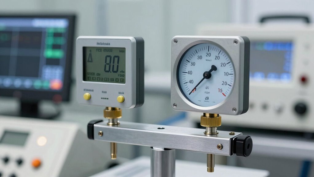
- Sensor calibration tools and diagnostic equipment for pre-session checks
- Spare components including spark plugs, ignition wires, and fuel system parts
- Safety hardware including wheel lock keys and securing fasteners
Evaluating suppliers based on product reliability, technical support, and warranty coverage secures seamless integration with Hyper Power’s dynamometer systems.
Establishing relationships with trusted vendors minimises downtime and secures access to certified replacement parts when needed.
Regular software updates ensure your dynamometer maintains peak performance and compatibility with evolving testing standards throughout its operational lifecycle.
Moving Your Pods Around the Shop: Storage and Repositioning
Hub dynamometer systems distinguish themselves through exceptional portability, a capability that fundamentally changes how workshops organise their testing operations and facility layouts. Each pod measures 50 cm × 90 cm × 90 cm and weighs only 400 kg, enabling straightforward repositioning without specialised equipment.
Three wheels per pod, including one steering wheel, facilitate directional alignment and manual movement within workshop spaces.
Pod Mobility Advantages
Mechanical handles integrated into each pod structure support safe relocation via van transport or pallet systems. Lifter hooks allow seamless transfers between locations, eliminating permanent floor anchoring requirements.
This mobility means your testing equipment travels with your business needs.
Storage Solutions
When not in use, pods disconnect easily and store away, freeing useful shop space for other operations.
No dedicated installation space remains permanently occupied, maximising workshop efficiency and flexibility for growing operations.